1. Introduction
Thank you for choosing the conecto Monitor TV Wall Mount. This manual provides essential information for the safe and correct installation, operation, and maintenance of your wall mount. Please read these instructions carefully before installation and retain them for future reference.
Safety Information
- Ensure the mounting surface can safely support the combined weight of the mount and your display.
- Do not exceed the maximum weight capacity of 20 kg (44 lbs).
- This mount is designed for displays between 13 and 32 inches.
- Always use appropriate safety equipment during installation.
- If you are unsure about any part of the installation, consult a qualified professional.
2. Package Contents
Please verify that all components listed below are present and undamaged before beginning installation. If any parts are missing or damaged, please contact conecto customer support.
- Wall Mount Assembly
- Wall Plate Screws and Anchors
- Display Mounting Screws (various sizes for VESA compatibility)
- Washers and Spacers
- Spirit Level
- Wrench
- Installation Manual

Figure 2.1: All components included in the package. Ensure all parts are present before proceeding with installation.
3. Specifications
| Model Number | SA-FM13-100 |
| Compatible Screen Sizes | 13 - 32 inches |
| Maximum Weight Capacity | 20 kg (44 lbs) |
| VESA Compatibility | 75x75 mm, 100x100 mm |
| Tilt Range | +5° to -15° |
| Swivel Range | Up to 90° left/right |
| Wall Clearance | 62 mm - 194 mm |
| Material | Stainless Steel |
| Product Dimensions (folded) | 5.12 x 9.06 x 2.36 inches |
| Item Weight | 1.56 pounds |
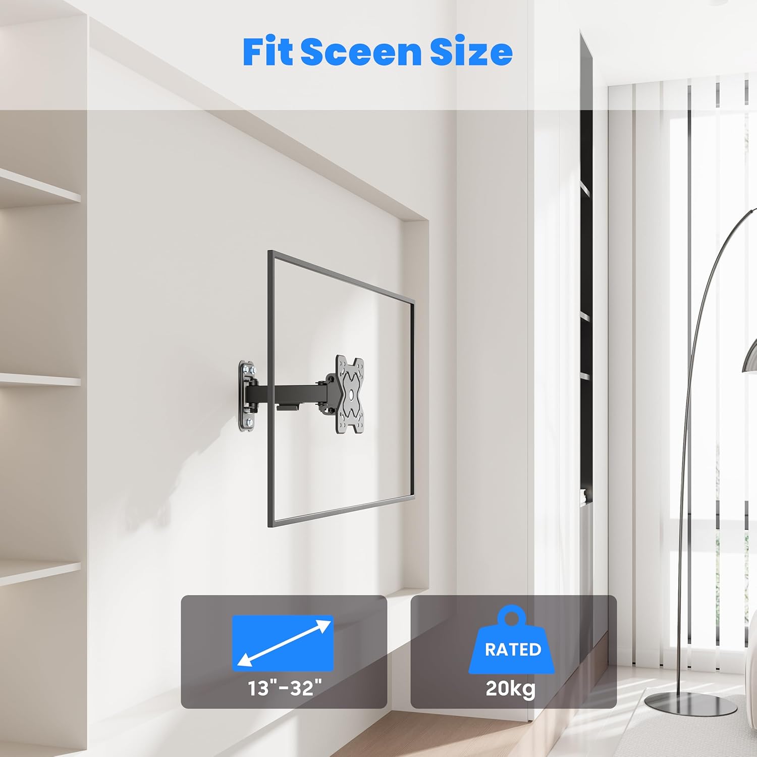
Figure 3.1: The mount supports displays from 13 to 32 inches and up to 20 kg.
4. Setup and Installation
4.1 Before Installation
Before mounting, carefully plan the location of your display. Consider viewing angles, cable management, and the type of wall you are mounting to.
Wall Type Compatibility
This mount is suitable for installation on:
- Wooden Walls (single stud)
- Solid Brick Walls
- Concrete Walls
Note: Do not install on drywall alone without securing to a stud or using appropriate anchors for the wall material.

Figure 4.1: Compatible wall types for secure installation.
VESA Compatibility
The mount supports VESA patterns of 75x75 mm and 100x100 mm. Verify your display's VESA pattern before proceeding.
4.2 Installation Steps
Refer to the included illustrated installation guide for detailed, step-by-step instructions. A general overview of the process is as follows:
- Mark Drilling Locations: Use the wall plate as a template to mark the drilling points on your wall. Use the included spirit level to ensure accuracy.
- Drill Holes: Drill pilot holes at the marked locations according to the recommended drill bit size for your wall type. Insert wall anchors if necessary.
- Attach Wall Plate: Secure the wall plate to the wall using the provided screws. Ensure it is firmly attached and level.
- Attach VESA Plate to Display: Attach the VESA mounting plate to the back of your monitor or TV using the appropriate screws and spacers from the hardware kit.
- Hang Display: Carefully lift the display with the attached VESA plate and hook it onto the wall mount arm. Secure any safety mechanisms as per the detailed guide.
5. Operating Instructions
Once installed, your conecto wall mount allows for flexible adjustment of your display.
5.1 Tilt Adjustment
The mount allows for a tilt range of +5° (upwards) to -15° (downwards). To adjust the tilt, loosen the tilt adjustment screws on the VESA plate, set the desired angle, and then securely tighten the screws to hold the position.
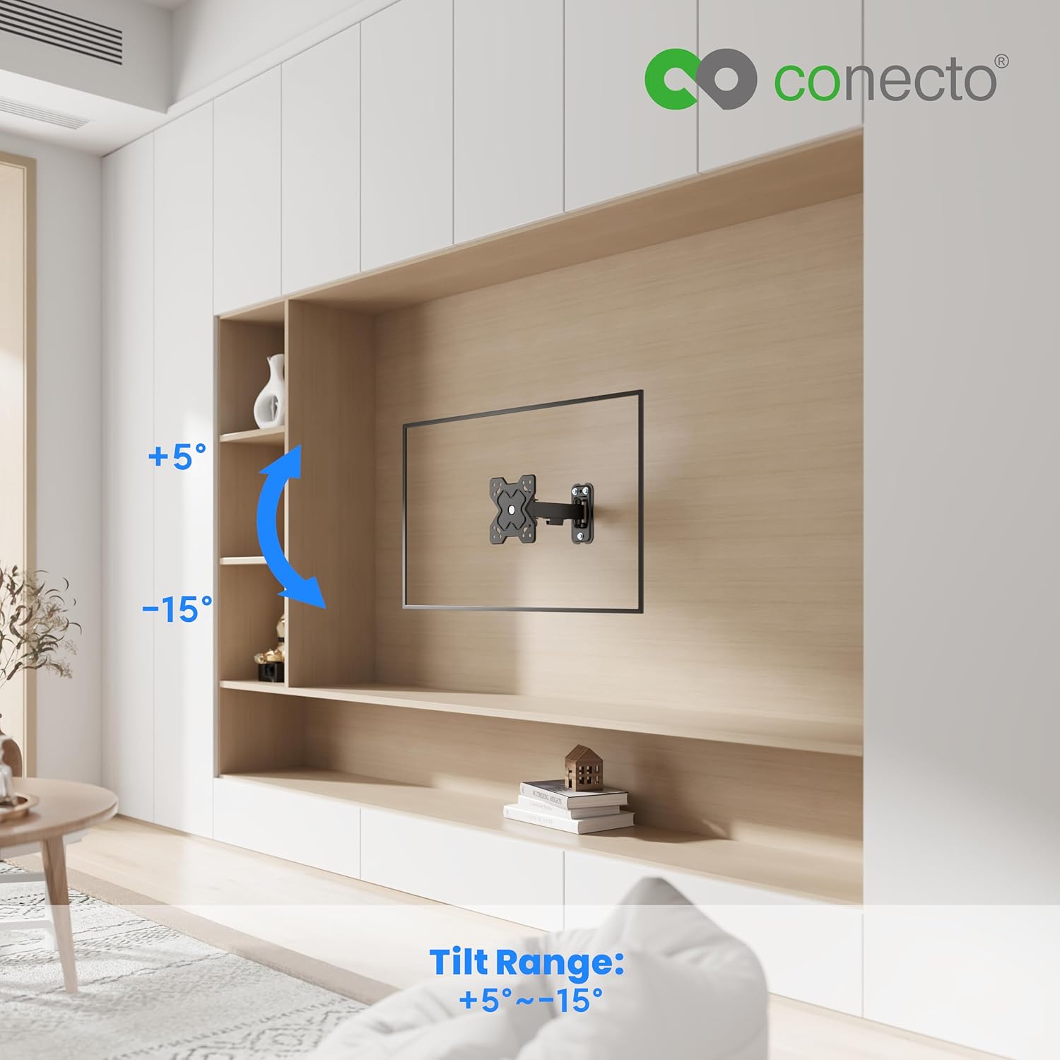
Figure 5.1: Tilt range of +5° to -15° for optimal viewing.
5.2 Swivel Adjustment
The mount can swivel up to 90° to the left and 90° to the right. To adjust the swivel, gently push or pull the display to the desired horizontal angle. The friction joints are designed to hold the position.

Figure 5.2: Swivel range of up to 90° left and right.
5.3 Wall Clearance
The mount provides a wall clearance that can be adjusted between 62 mm and 194 mm. This allows for better air circulation behind the display and facilitates access to ports and cables.

Figure 5.3: Adjustable wall clearance for ventilation and port access.
6. Maintenance
Regular maintenance ensures the longevity and safe operation of your wall mount.
- Cleaning: Wipe the mount with a soft, dry cloth. Avoid abrasive cleaners or solvents that could damage the finish.
- Check Connections: Periodically check all screws and bolts to ensure they remain tight and secure. Re-tighten if necessary.
- Inspect for Wear: Inspect the mount for any signs of wear, damage, or corrosion. If any issues are found, discontinue use and contact customer support.
7. Troubleshooting
If you encounter issues with your wall mount, refer to the following common problems and solutions:
- Mount is not level: Ensure the wall plate was installed level. If not, you may need to re-drill or adjust. The VESA plate on the display may also have a slight rotational adjustment feature; check your specific display's manual.
- Display sags or does not hold position: Ensure all tilt and swivel adjustment screws are sufficiently tightened. Verify that the display's weight does not exceed the mount's maximum capacity.
- Difficulty adjusting movement: Check for any obstructions. Ensure all moving parts are clean and free of debris. Do not force adjustments.
- Missing parts: Refer to the 'Package Contents' section. If parts are missing upon unboxing, contact conecto customer support immediately.
8. Warranty and Support
For warranty information, please refer to the documentation provided with your purchase or visit the official conecto website. If you require technical assistance or have questions not covered in this manual, please contact conecto customer support through their official channels.
Manufacturer: Satchef GmbH


