1. Introduction
This manual provides comprehensive instructions for the safe and efficient operation, installation, and maintenance of your HH8BWL UX-52 400W Multi-Function Digital Display Motor Speed Controller. Please read this manual thoroughly before using the device to ensure proper function and to prevent damage or injury. Keep this manual for future reference.
2. Safety Information
Always observe the following safety precautions to prevent electric shock, injury, or damage to the equipment:
- Ensure the power supply is disconnected before making any wiring connections or performing maintenance.
- This device operates on AC220V. Incorrect voltage can cause severe damage.
- Only qualified personnel should perform installation and wiring.
- Do not operate the controller in wet or damp conditions.
- Ensure proper grounding to prevent electrical hazards.
- Do not exceed the rated power of 400W for connected motors.
3. Product Overview
The HH8BWL UX-52 is a multi-function digital display motor speed controller designed for single-phase AC motors up to 400W. It features precise speed regulation, forward and reverse control, and a digital display for monitoring. The controller is equipped with various buttons for mode selection and parameter adjustment.

Figure 3.1: Front view of the HH8BWL UX-52 400W Motor Speed Controller, showing the digital display, control buttons, and speed regulating potentiometer.
3.1. Button and Display Functions
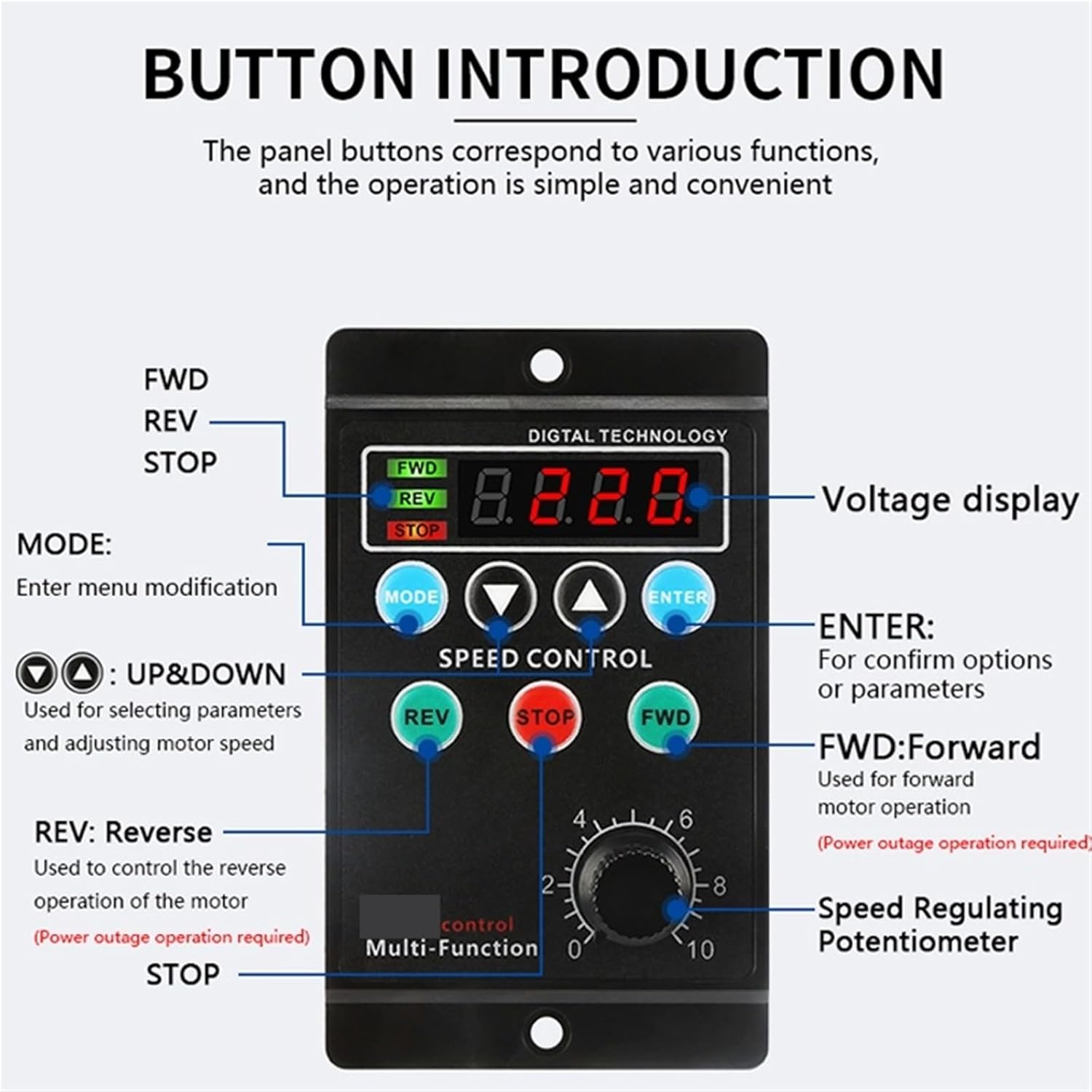
Figure 3.2: Detailed diagram of the control panel, indicating the function of each button and the digital display.
- Digital Display: Shows voltage or other parameters.
- FWD Indicator: Illuminates when the motor is operating in forward direction.
- REV Indicator: Illuminates when the motor is operating in reverse direction.
- STOP Indicator: Illuminates when the motor is stopped.
- MODE Button: Used to enter menu modification for settings.
- UP/DOWN Buttons (▲/▼): Used for selecting parameters and adjusting motor speed.
- ENTER Button: Used to confirm options or parameters.
- REV Button: Controls the reverse operation of the motor. (Requires power outage operation for some models/settings).
- STOP Button: Stops the motor.
- FWD Button: Controls the forward operation of the motor.
- Speed Regulating Potentiometer: Adjusts the motor speed from 0 to 10.
4. Specifications
| Feature | Specification |
|---|---|
| Model Number | UX-52 |
| Rated Power | 400W |
| AC Voltage | 208-230 / 240 V |
| Phase | Single-phase |
| Efficiency | IE 1 |
| Certification | CE |
| Item Weight | 1.76 ounces (approx. 50g) |
| Unit Dimensions (approx.) | 90mm (H) x 85mm (D) x 52mm (W) |
| Manufacturer | HH8BWL |

Figure 4.1: Physical dimensions of the UX-52 motor speed controller.
5. Setup
5.1. Mounting
The controller is designed for panel mounting. Ensure adequate ventilation around the unit to prevent overheating. Use appropriate screws to secure the controller through the mounting holes on its flanges.
5.2. Wiring Connections
Refer to the wiring diagram below for correct connections. Incorrect wiring can damage the controller and the motor.

Figure 5.1: Wiring terminal block on the rear of the controller.
Terminal Descriptions:
- AC-L, AC-N: AC 220V Power Input. Connect the live and neutral wires of your AC power supply here.
- U1, U2, Z1, Z2: Motor Connection Terminals. These terminals are for connecting the motor windings. Consult your motor's wiring diagram for specific connections.
- S1, S2: Speed Feedback/Control. These may be used for external speed control signals or feedback, depending on the motor type and application.
- 0V: Common ground for control signals.
- K1, K2: External Control Inputs. These terminals can be used for external switches to control FWD/REV functions.
- FWD, REV: Forward and Reverse control signals.
Warning: Ensure all connections are secure and insulated to prevent short circuits and electrical hazards.
6. Operating Instructions
6.1. Power On/Off
After ensuring all wiring is correct and secure, connect the AC220V power supply. The digital display will illuminate.
6.2. Speed Adjustment
Rotate the Speed Regulating Potentiometer knob (labeled 0-10) clockwise to increase motor speed and counter-clockwise to decrease it. The digital display may show the current speed setting or related parameter.
6.3. Direction Control
- Press the FWD button to operate the motor in the forward direction. The FWD indicator will light up.
- Press the REV button to operate the motor in the reverse direction. The REV indicator will light up. Note: Some configurations may require a power cycle or stopping the motor before changing direction.
- Press the STOP button to halt motor operation. The STOP indicator will light up.
6.4. Mode and Parameter Settings
The MODE button allows access to various settings and parameters. Use the UP (▲) and DOWN (▼) buttons to navigate through options or adjust values. Press ENTER to confirm your selection or save changes. Refer to the specific parameter list (if provided separately or on the device) for detailed mode functions.
7. Maintenance
Regular maintenance ensures the longevity and optimal performance of your motor speed controller.
- Cleaning: Periodically clean the exterior of the controller with a soft, dry cloth. Do not use liquid cleaners or solvents.
- Inspection: Regularly check all wiring connections for tightness and signs of wear or damage.
- Ventilation: Ensure that the ventilation openings are not obstructed to allow for proper heat dissipation.
- Environment: Operate the controller within its specified environmental conditions (temperature, humidity) to prevent damage.
8. Troubleshooting
If you encounter issues with your UX-52 motor speed controller, refer to the following common problems and solutions:
| Problem | Possible Cause | Solution |
|---|---|---|
| Controller does not power on / Digital display is off. | No power supply; Incorrect wiring; Blown fuse (internal). | Check AC220V power connection. Verify wiring. Contact support if fuse is suspected. |
| Motor does not run. | Motor wiring incorrect; Speed potentiometer at minimum; STOP button engaged; Motor fault. | Check motor connections. Increase speed with potentiometer. Press FWD/REV. Test motor independently. |
| Motor speed is inconsistent or incorrect. | Incorrect parameter settings; Motor overload; Potentiometer fault. | Check MODE settings. Reduce motor load. Inspect potentiometer. |
| Motor direction cannot be changed. | Incorrect wiring; Controller in a locked mode; Motor not stopped before direction change. | Verify motor wiring for FWD/REV. Ensure motor is stopped before changing direction. Check MODE settings. |
| Overheating of controller. | Insufficient ventilation; Overload; Ambient temperature too high. | Ensure clear ventilation. Reduce motor load. Operate in cooler environment. |
If the problem persists after attempting these solutions, please contact customer support.
9. Warranty and Support
For warranty information, please refer to the terms and conditions provided at the point of purchase or contact your seller directly. HH8BWL is committed to providing quality products and support.
For technical assistance or further inquiries, please contact the manufacturer or your authorized distributor. When contacting support, please have your product model (UX-52) and purchase details available.


