1. Introduction
This user manual provides comprehensive instructions for the installation, configuration, and operation of the Real HD 24 Port 2.5Gb PoE+ Managed Ethernet Network Switch. This device is designed to provide high-speed network connectivity and Power over Ethernet (PoE) capabilities for various network devices, including IP cameras, wireless access points, and VoIP phones.
2. Product Overview
2.1 Key Features
- 24 x 2.5Gbps RJ45 Ports with PoE+ capability.
- 4 x PoE++ Ports (Port 1-4) supporting up to 90W each.
- 2 x 10G SFP+ Uplink Ports for high-bandwidth connections.
- Total PoE power budget of 500W.
- IEEE 802.3bt/at/af compliance.
- 160G Bandwidth and 119.04Mbps Forwarding Rate.
- Web-managed interface for advanced configuration (VLAN, QoS, Link Aggregation, Spanning Tree Protocol, Multicast).
- Sturdy metal housing with built-in cooling fans.
- Supports both desktop and 19-inch rack mount installations.
2.2 Front Panel Layout

Figure 2.2.1: Front Panel of the 24 Port 2.5Gb PoE+ Managed Ethernet Network Switch. This image displays the 24 RJ45 ports, 2 SFP+ ports, LED indicators for power and link status, and the model number.
The front panel features 24 RJ45 ports, with ports 1-4 highlighted for their PoE++ capabilities. Additionally, two 10G SFP+ ports are located on the right side for high-speed fiber optic connections. LED indicators provide status information for power, link, and activity for each port.
2.3 Power over Ethernet (PoE) Capabilities

Figure 2.3.1: PoE Power Distribution. This diagram illustrates that ports 1-4 support up to 90W (PoE++), while ports 5-24 support up to 30W (PoE+), with a total power budget of 500W. Examples of compatible devices like access points, IP cameras, and VOIP phones are shown.
The switch provides robust Power over Ethernet capabilities. Ports 1-4 are PoE++ compliant, delivering up to 90W per port, suitable for high-power devices. Ports 5-24 are PoE+ compliant, providing up to 30W per port. The total PoE power budget for the switch is 500W. This allows for direct power and data transmission to compatible devices over a single Ethernet cable.
2.4 Network Speed and Bandwidth

Figure 2.4.1: Network Speed Capabilities. This image highlights the switch's ability to deliver 2.5Gbps speeds, which is 2.5 times faster than standard 1Gbps networks. It also shows compatibility with CAT6, CAT6a, and CAT7 cables for optimal performance, and the 10G SFP+ ports for even higher speeds.
This switch offers 2.5Gbps speeds on its RJ45 ports, providing 2.5 times the throughput of traditional 1Gbps networks. For optimal performance at 2.5Gbps, it is recommended to use CAT6, CAT6a, or CAT7 Ethernet cables. The two 10G SFP+ ports enable ultra-high-speed connections to backbone networks or servers, supporting a total bandwidth of 160Gbps.
2.5 Detailed Port and Specification Overview

Figure 2.5.1: Detailed Port and Specification Overview. This image provides a closer look at the 24 x 2.5Gbps RJ45 ports, their LED indicators, the 2 x 10Gb SFP+ ports, and key performance metrics such as 160Gbps bandwidth, 119.04Mbps forwarding rate, 16K MAC address table, and 12Mbit packet buffer.
This image provides a comprehensive summary of the switch's physical interfaces and core performance metrics. It details the 24 x 2.5Gbps RJ45 ports, their link/activity LED behaviors (Green for 2.5G, Yellow for 10/100/1000M, Flashing for Data Transmitting, Off for Link Not Working), and the power input requirements. Key performance indicators like 160Gbps bandwidth, 119.04Mbps forwarding rate, 16K MAC address table, and 12Mbit packet buffer are also highlighted, along with the PoE power distribution for ports 1-4 (90W) and 5-24 (30W).
3. Setup and Installation
3.1 Package Contents
Verify that your package contains the following items:
- Real HD 24 Port 2.5G Web Managed PoE+ Switch
- Power Cord
- Rack Mount Brackets (for 19-inch rack installation)
- Screws for rack mounting
- User Manual (this document)
3.2 Physical Installation
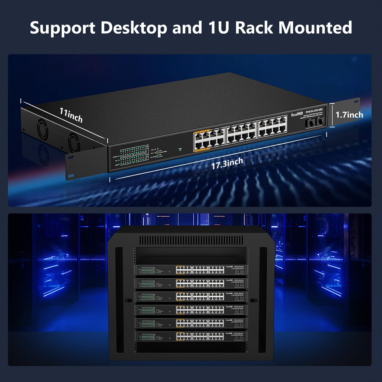
Figure 3.2.1: Installation Options. This image displays the dimensions of the switch (17.3 x 11 x 1.7 inches) and demonstrates its compatibility with both desktop placement and standard 19-inch rack mounting using the included brackets.
The switch supports both desktop placement and 19-inch rack mounting. For rack installation, attach the provided rack mount brackets to the sides of the switch using the included screws, then secure the switch into a standard 19-inch server rack.
3.3 Connecting the Switch
- Power Connection: Connect the power cord to the AC input port on the rear of the switch and plug it into a standard AC power outlet (100-240V, 50/60Hz).
- Network Devices: Connect your network devices (computers, servers, IP cameras, access points, etc.) to the RJ45 ports on the front panel using Ethernet cables. Ensure that for 2.5Gbps speeds, CAT6 or higher pure copper Ethernet cables are used.
- Uplink Connections: For high-speed connections to your core network or other switches, use appropriate SFP+ transceivers (not included) in the 10G SFP+ ports and connect them with fiber optic cables.
3.4 Initial Web Management Access

Figure 3.4.1: Web Management Login. This image displays the default login credentials for accessing the switch's web management interface: Default IP: 192.168.2.1, User Name: admin, Password: admin.
To access the web management interface:
- Ensure your computer is connected to one of the switch's RJ45 ports.
- Configure your computer's IP address to be in the same subnet as the switch (e.g., 192.168.2.x, with a subnet mask of 255.255.255.0).
- Open a web browser and enter the default IP address: 192.168.2.1
- At the login prompt, enter the default credentials:
- User Name: admin
- Password: admin
- It is highly recommended to change the default password immediately after the first login for security purposes.
4. Operating Instructions (Web Management)
The web-managed interface provides comprehensive control over the switch's features. After logging in, you can monitor device/port status and configure various network settings.
4.1 Basic Management Features

Figure 4.1.1: Overview of Basic Management Features. This image illustrates the range of configurable features accessible via the web interface, designed to optimize network efficiency.
The switch offers a suite of management features to optimize network performance and security. These include:
- VLAN (Virtual Local Area Network): Segment your network for improved security and performance.
- QoS (Quality of Service): Prioritize network traffic for critical applications.
- Link Aggregation (LACP/Static): Combine multiple physical links into a single logical link for increased bandwidth and redundancy.
- Spanning Tree Protocol (STP/RSTP/MSTP): Prevent network loops.
- Multicast (IGMP Snooping): Optimize multimedia traffic delivery.
- Jumbo Frame: Support for larger Ethernet frames to improve throughput.
- MAC Address Table Management: View and manage MAC addresses.
4.2 VLAN Configuration

Figure 4.2.1: VLAN for Higher Security. This image demonstrates how VLANs (VLAN1, VLAN2) can be used to logically separate network traffic, enhancing security and management within a business network.
VLANs allow you to logically group devices on your network, regardless of their physical location. This enhances security by isolating traffic and improves network efficiency. The switch supports up to 31 static VLAN groups and configurable VLAN IDs from 1-4094. Refer to the web management interface's VLAN section for detailed configuration steps.
4.3 QoS (Quality of Service)

Figure 4.3.1: QoS for Fluent Online Experience. This image illustrates how administrators can prioritize different types of network traffic, such as voice and video, to ensure smooth and lag-free performance.
QoS features enable you to prioritize certain types of network traffic, such as voice or video, to ensure smooth and uninterrupted performance. This is crucial for applications sensitive to latency and packet loss. The switch supports SP and WRR scheduling and up to 8 queues per port. Configure QoS settings through the web interface to optimize your network for specific applications.
4.4 IGMP Snooping for Multicast Optimization

Figure 4.4.1: IGMP Snooping for Multicast Optimization. This image visually represents how IGMP Snooping enhances the delivery of multimedia traffic, leading to a better network experience, particularly for services like IPTV.
IGMP Snooping is a feature that optimizes the delivery of multicast traffic, such as IPTV or video conferencing streams. By intelligently forwarding multicast packets only to the ports that have requested them, it prevents unnecessary flooding of traffic across the network, conserving bandwidth and improving overall performance.
5. Maintenance
5.1 General Care
- Keep the switch in a well-ventilated area to ensure proper airflow for the built-in cooling fans.
- Avoid exposing the switch to extreme temperatures, humidity, or direct sunlight. The operating temperature range is 32 to 104°F (0 to 40°C).
- Clean the exterior of the switch with a soft, dry cloth. Do not use liquid cleaners or aerosols.
- Ensure all cable connections are secure and free from damage.
5.2 Firmware Updates
Periodically check the Real HD official website for available firmware updates. Firmware updates can provide new features, performance improvements, and security enhancements. Follow the instructions provided with the firmware update package carefully to avoid damaging the device.
6. Troubleshooting
6.1 Common Issues and Solutions
| Problem | Possible Cause | Solution |
|---|---|---|
| No Power LED indication | Power cord not connected or power outlet issue. | Ensure the power cord is securely connected to the switch and a working power outlet. Test the outlet with another device. |
| No Link/Activity LED for a connected device | Incorrect cable, faulty cable, or device not powered on/configured. | Verify the Ethernet cable is correctly connected at both ends. Try a different cable. Ensure the connected device is powered on and functioning correctly. |
| PoE device not receiving power | Device not PoE compliant, cable issue, or switch PoE budget exceeded. | Ensure the device is IEEE 802.3bt/at/af compliant. Check the Ethernet cable. Verify the total power consumption of connected PoE devices does not exceed the 500W budget. Note: Does not support passive 24V PoE devices. |
| Cannot access web management interface | Incorrect IP address, network configuration, or browser issue. | Verify your computer's IP address is in the same subnet as the switch (192.168.2.x). Clear browser cache or try a different browser. Ensure the switch is powered on. |
| Slow network speed | Cable quality, device compatibility, or network congestion. | Ensure CAT6 or higher pure copper Ethernet cables are used for 2.5Gbps connections. Verify connected devices support 2.5Gbps. Check for excessive network traffic or loops. |
| Audible fan noise | Normal operation for active cooling. | This model includes built-in fans for cooling, which may produce audible noise, especially under load. This is normal operation and ensures optimal temperature for the device. |
7. Specifications
| Feature | Description |
|---|---|
| Model Number | 24 Port 2.5GB PoE Web Managed Switch |
| Switch Type | Managed, PoE+, PoE++ |
| Number of Ports | 24 x 2.5Gbps RJ45 (PoE+), 2 x 10G SFP+ |
| PoE Standard | IEEE 802.3bt/at/af |
| PoE Power Output | Port 1-4: Up to 90W each (PoE++); Port 5-24: Up to 30W each (PoE+) |
| Total PoE Budget | 500W |
| Bandwidth | 160Gbps |
| Forwarding Rate | 119.04Mbps |
| MAC Address Table Size | 16K |
| Packet Buffer | 12Mbit |
| Case Material | Metal |
| Dimensions (L x W x H) | 17.3 x 11 x 1.7 inches (approx. 43.9 x 27.9 x 4.3 cm) |
| Item Weight | 10.43 pounds (approx. 4.73 kg) |
| Operating Temperature | 32 to 104°F (0 to 40°C) |
| Power Input | AC 100-240V, 50/60Hz |
| Included Components | 24 Port 2.5G Web Managed PoE+ Switch, Power Cord, Rack Mount Brackets |
8. Warranty and Technical Support
Real HD provides technical support for this product. For any technical assistance, troubleshooting, or warranty inquiries, please contact our US-based technical support team.
- Technical Support Hours: 9 AM - 5 PM CST (Central Standard Time)
- Contact: Please refer to the contact information provided on the product packaging or the official Real HD website.
Please have your product model number and purchase details ready when contacting support.