1. Introduction
This manual provides detailed instructions for the installation, operation, and maintenance of the Autonics TZN4S-14C Standard Type Temperature Controller. The TZN4S-14C is a high-performance digital temperature controller designed for precise temperature regulation in various industrial applications. Please read this manual thoroughly before using the product to ensure correct and safe operation.
2. Key Features
- Display Method: 4-digit 7-segment LED for clear readings.
- Control Methods: Supports ON/OFF control, P, PI, PD, PIDF, and PIDS control for versatile application.
- Input Specifications: Compatible with various thermocouples (K, J, E, T, R, S, N, W), RTD (DPt100Ω, JPt100Ω), and analog inputs (1-5VDC, 0-10VDC, DC4-20mA).
- Sampling Cycle: Fast 500ms sampling for responsive control.
- Control Output: Current output (DC4-20mA).
- Power Supply: Wide range 100-240VAC~ 50/60Hz.
3. Specifications
The following table outlines the detailed technical specifications of the Autonics TZN4S-14C Temperature Controller:
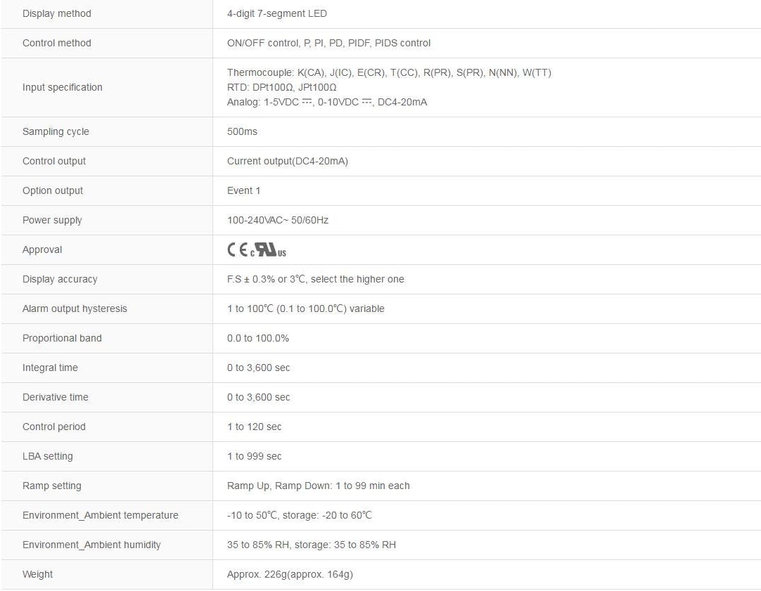
Image: Detailed specifications for the Autonics TZN4S-14C, including display method, control method, input specifications, sampling cycle, control output, power supply, approval, display accuracy, alarm output hysteresis, proportional band, integral time, derivative time, control period, LBA setting, ramp setting, environment ambient temperature, environment ambient humidity, and weight.
| Parameter | Description |
|---|---|
| Display Method | 4-digit 7-segment LED |
| Control Method | ON/OFF control, P, PI, PD, PIDF, PIDS control |
| Input Specification | Thermocouple: K(CA), J(IC), E(CR), T(CC), R(PR), S(PR), N(NN), W(TT) RTD: DPt100Ω, JPt100Ω Analog: 1-5VDC, 0-10VDC, DC4-20mA |
| Sampling Cycle | 500ms |
| Control Output | Current output (DC4-20mA) |
| Power Supply | 100-240VAC~ 50/60Hz |
| Display Accuracy | F.S ± 0.3% or 3°C, select the higher one |
| Alarm Output Hysteresis | 1 to 100°C (0.1 to 100.0°C) variable |
| Proportional Band | 0.0 to 100.0% |
| Integral Time | 0 to 3,600 sec |
| Derivative Time | 0 to 3,600 sec |
| Control Period | 1 to 120 sec |
| LBA Setting | 1 to 999 sec |
| Ramp Setting | Ramp Up, Ramp Down: 1 to 99 min each |
| Environment Ambient Temperature | -10 to 50°C, storage: -20 to 60°C |
| Environment Ambient Humidity | 35 to 85% RH, storage: 35 to 85% RH |
| Weight | Approx. 226g (approx. 164g) |
4. Installation and Wiring
Proper installation and wiring are crucial for the safe and accurate operation of the temperature controller. Ensure all power is disconnected before proceeding with installation.

Image: Front view of the Autonics TZN4S-14C Temperature Controller, showing the digital display for PV and SV, and control buttons (MD, AT, arrow keys).
4.1 Mounting
- Mount the controller in a location free from excessive vibration, dust, moisture, and corrosive gases.
- Ensure adequate ventilation around the unit to prevent overheating.
- Use the provided mounting brackets to secure the controller firmly into the panel cutout.
4.2 Electrical Connections
- Refer to the wiring diagram on the side of the unit or in the full technical datasheet for specific terminal connections.
- Power Supply: Connect the 100-240VAC~ 50/60Hz power supply to the designated power terminals.
- Sensor Input: Connect your chosen temperature sensor (thermocouple or RTD) or analog input to the corresponding input terminals. Ensure correct polarity for thermocouples and analog inputs.
- Control Output: Connect the device to be controlled (e.g., heater, valve) to the current output (DC4-20mA) terminals. Observe polarity.
- Ensure all wiring is securely fastened and insulated to prevent short circuits.
5. Operation
Once installed and wired, the controller is ready for operation. The front panel features a PV (Process Value) display, an SV (Set Value) display, and control buttons.
5.1 Power On
Apply power to the unit. The controller will perform a self-test, and then the PV display will show the current temperature, while the SV display will show the set target temperature.
5.2 Setting Parameters (SV)
- Press the MD (Mode) button to enter parameter setting mode.
- Use the Up and Down arrow buttons to adjust the Set Value (SV).
- Press MD again to confirm the setting and cycle through other parameters.
- Refer to the detailed programming manual for advanced parameter settings (e.g., P, I, D values, alarm settings).
5.3 Auto-Tuning (AT)
For optimal PID control, the Auto-Tuning function can automatically calculate the best PID constants for your system.
- Set the desired SV.
- Press and hold the AT button for a few seconds until the AT indicator lights up.
- The controller will cycle through heating and cooling to determine the optimal PID values. This process may take some time.
- Once complete, the AT indicator will turn off, and the new PID values will be saved.
6. Maintenance
Regular maintenance ensures the longevity and reliable performance of your temperature controller.
- Cleaning: Periodically clean the front panel with a soft, dry cloth. Do not use abrasive cleaners or solvents.
- Inspection: Regularly inspect wiring connections for looseness or damage. Check for any signs of overheating or discoloration.
- Environment: Ensure the operating environment remains within the specified temperature and humidity ranges.
7. Troubleshooting
This section provides solutions to common issues you might encounter. For problems not listed here, contact technical support.
| Problem | Possible Cause | Solution |
|---|---|---|
| No power to the unit | Power supply disconnected or faulty fuse. | Check power connections and circuit breaker. Replace fuse if necessary. |
| PV display shows 'HHHH' or 'LLLL' | Sensor open circuit or short circuit, or incorrect sensor type selected. | Check sensor wiring and connections. Verify sensor type matches controller settings. |
| Temperature not controlled accurately | Incorrect PID parameters, control output issue, or external disturbance. | Perform Auto-Tuning. Check control output wiring. Ensure stable operating environment. |
| Output not activating | Wiring error, output parameter setting incorrect, or load fault. | Verify output wiring. Check output mode and settings in parameter menu. Test the load device independently. |
8. Warranty and Support
For warranty information, please refer to the documentation provided with your purchase or contact the seller directly. Technical support can be obtained through the manufacturer's official channels or your authorized distributor.