1. Introduction
The PDDAXLQUE DX-BT24-SET is an ultra-low power Bluetooth Low Energy (BLE) 5.1 module designed for various applications requiring wireless communication. This module, based on the DA14531 chip, offers a long communication range of up to 90 meters and supports serial communication data transfer at speeds up to 10K Bytes/s. Its compact size and low power consumption make it suitable for battery-powered devices and embedded systems. This manual provides detailed instructions for setting up, operating, and troubleshooting your DX-BT24-SET module.
Key Features:
- Renesas DA14531 & BLE 5.1
- Communication Distance: 90m
- Serial communication data transfer
- Abundant AT commands for configuration
- Transmission rate: 10K Byte/s
- Power consumption as low as 2 µA (hibernation)
- Optional on-board or external antenna
- Module Size: 37.5(L) x 15.7(W) x 4.0(H) mm
- Transmit Power: -19.5 ~ +2.5dBm
- Working temperature: -40 ~ +85°C
- Shield Protection: Antistatic & Dustproof
- Supports PC, iOS, Android transmission
- BQB, CE, FCC, IC, SRCC, ROHS certified
2. Safety Information
Please read and understand the following safety precautions before using the DX-BT24-SET module:
- Ensure proper voltage supply (3.3V) to prevent damage to the module.
- Handle the module with care to avoid electrostatic discharge (ESD) damage.
- Do not expose the module to extreme temperatures, humidity, or corrosive environments.
- Observe correct polarity when connecting power and data lines.
- This module is intended for integration into other devices. Ensure the final product complies with all relevant regulations.
3. Package Contents
The DX-BT24-SET package typically includes the following components:
- 1x DX-BT24 Bluetooth Module
- 1x USB to TTL Adapter Board (for development kit)
- 1x USB Cable (for development kit)

Image 3.1: Contents of the DX-BT24-SET Developer Package, showing the BT24 module, a USB to TTL adapter board, and a USB cable.
4. Product Overview
The DX-BT24 module is a compact and efficient solution for integrating BLE 5.1 connectivity into your projects. It features a robust design with an RF shielding cover for strong anti-interference and EMC compatibility. The module supports both onboard and external antenna options.
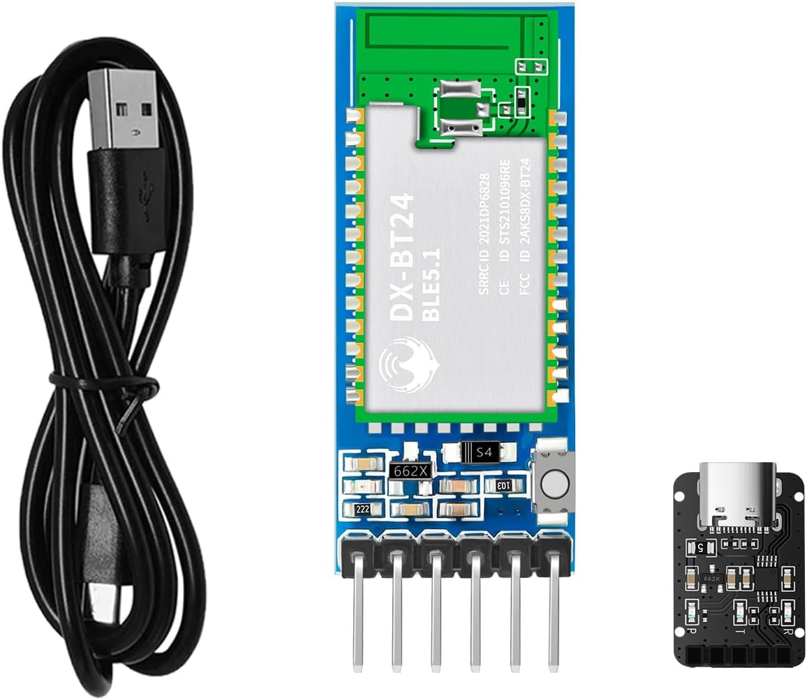
Image 4.1: The DX-BT24-SET Bluetooth module, shown alongside a USB cable and a USB to TTL adapter board, illustrating the complete set.
5. Setup and Pinout
The DX-BT24 module communicates via a UART serial port. Understanding the pinout is crucial for correct integration.
5.1 Pin Description
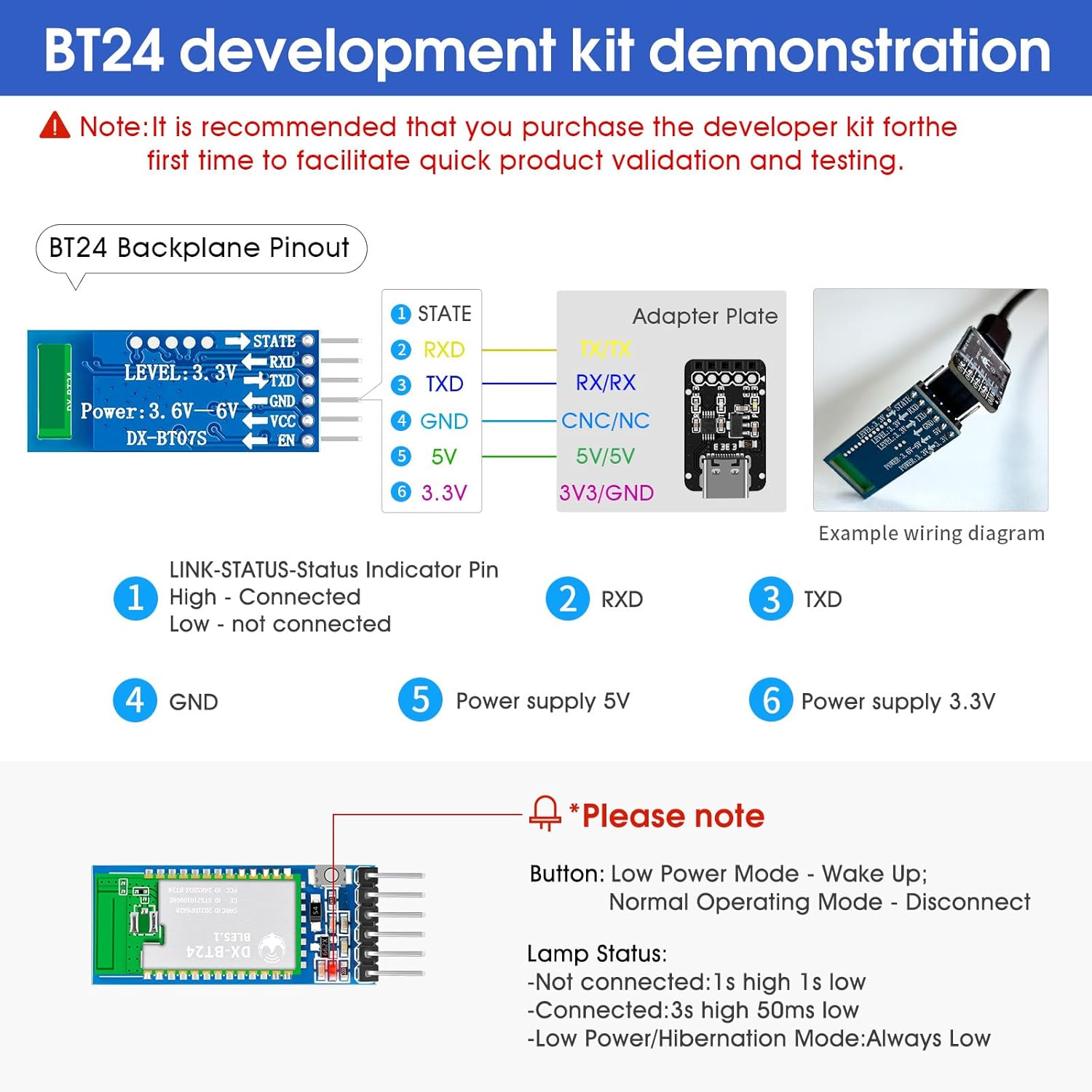
Image 5.1: Detailed pinout diagram for the DX-BT24 module and an example wiring diagram connecting it to an adapter plate.
The module features the following pins:
- STATE: Link status indicator pin. High indicates connected, Low indicates not connected.
- RXD: Receive Data pin for UART communication.
- TXD: Transmit Data pin for UART communication.
- GND: Ground connection.
- 5V: 5V power supply input (typically for adapter board, module itself uses 3.3V).
- 3.3V: 3.3V power supply input for the module.
5.2 Wiring Example
When using the development kit, connect the DX-BT24 module to the USB to TTL adapter board as follows:
- Connect the RXD pin of the DX-BT24 module to the TXD pin of the adapter board.
- Connect the TXD pin of the DX-BT24 module to the RXD pin of the adapter board.
- Connect the GND pin of the DX-BT24 module to the GND pin of the adapter board.
- Connect the 3.3V pin of the DX-BT24 module to the 3.3V output of the adapter board.
- Connect the USB cable from the adapter board to your computer.
Note on LED Status:
- Not connected: 1s high, 1s low.
- Connected: 3s high, 50ms low.
- Low Power/Hibernation Mode: Always Low.
6. Operating Instructions
The DX-BT24 module facilitates communication between devices via its UART serial port and the BLE protocol.
6.1 Serial Communication
The module supports multiple serial port baud rates: 2400, 9600, 19200, 38400, 57200, 115200. The serial port transmission speed can reach up to 10K Bytes/s.

Image 6.1: Diagrams illustrating various serial communication applications: phone to module, computer to module, and module to module.
Communication Scenarios:
- Phone APP to Bluetooth Module: Use a dedicated mobile application (e.g., DX-SMART APP or a self-developed APP) to search for and connect to the DX-BT24 module. Data is then exchanged via the BLE connection.
- Computer Software to Bluetooth Module: Connect the module to a computer via a USB to TTL adapter. Use serial port software (e.g., Serial Assistant or custom software) to communicate with the module.
- Module to Module Communication: Two DX-BT24 modules can communicate directly with each other, with one configured as a master and the other as a slave.
Important Note: The DX-BT24 Bluetooth module supports the BLE protocol. It cannot be directly searched and connected by a phone's native Bluetooth settings or a computer's standard Bluetooth interface. You must use a specific application (either your own developed APP or a test APP provided by the manufacturer) to establish a connection. For computer connectivity, a master module or a CP11 adapter is required to interface with serial port software.
7. AT Commands
The DX-BT24 module features a comprehensive set of AT commands for configuration and control. These commands allow you to query and set various parameters of the module without needing to develop complex Bluetooth firmware.
7.1 Common AT Commands
| AT Command | Command Description |
|---|---|
| AT+VERSION | Query version number |
| AT+LADDR | Query MAC Address |
| AT+NAME | Query Bluetooth Name |
| AT+NAME<name> | Setting Bluetooth Name |
| AT+NAMAC | Query Bluetooth Parameters |
| AT+NAMAC <param> | Setting Bluetooth Parameters |
| AT+STOP | Query Serial Stop Bit |
| AT+STOP <param> | Setting the Serial Stop Bit |
| AT+PARI | Query serial port parity bit |
For a complete list of AT commands and their detailed usage, please refer to the official product information packages and technical documentation provided by the manufacturer.
8. Power Consumption
The DX-BT24 module is designed for ultra-low power operation, making it ideal for battery-powered applications. It features different power modes to optimize energy usage.
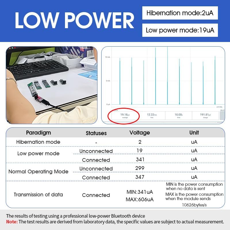
Image 8.1: Graph and table detailing the power consumption of the DX-BT24 module in various operating modes, including hibernation and data transmission.
Power Consumption Overview:
- Hibernation mode: As low as 2 µA.
- Low power mode (unconnected): Approximately 19 µA.
- Normal Operating Mode (connected, idle): Around 341 µA.
- Data Transmission (connected): Minimum 341 µA, Maximum 606 µA (at 10626 bytes/s).
These figures are derived from laboratory data and are subject to actual measurement conditions.
9. Specifications
| Feature | Specification |
|---|---|
| Model Number | DX-BT24-SET |
| Bluetooth Version | BLE 5.1 |
| Chipset | DA14531 |
| Communication Range | Up to 90 meters |
| Data Transfer Rate | Up to 10K Bytes/s (serial port) |
| Operating Voltage | 3.3V |
| Power Consumption (Hibernation) | As low as 2 µA |
| Power Consumption (Working) | As low as 19 µA (unconnected) |
| Module Dimensions (L x W x H) | 37.5 x 15.7 x 4.0 mm |
| Transmit Power | -19.5 ~ +2.5dBm |
| Operating Temperature | -40°C to +85°C |
| Hardware Interface | Bluetooth, UART |
| Compatible Devices | Laptop, Smartphone (via APP) |
| Certifications | BQB, CE, FCC, IC, SRCC, ROHS |
10. Troubleshooting
If you encounter issues with your DX-BT24-SET module, consider the following common troubleshooting steps:
- Module not powering on: Verify power supply connections and ensure the correct 3.3V voltage is applied.
- Cannot connect via phone/computer: Remember that the DX-BT24 uses BLE and requires a specific application (not native Bluetooth settings) for connection. For computers, a master module or CP11 adapter is needed.
- No data transmission: Check UART wiring (RXD to TXD, TXD to RXD), baud rate settings, and ensure the module is in a connected state (STATE LED indicator).
- AT commands not responding: Ensure the module is in command mode (if applicable, refer to full AT command documentation) and that serial communication settings (baud rate, parity, stop bits) are correct.
- Short communication range: Check for environmental interference or obstructions. Ensure the antenna is properly connected (if using an external antenna).
11. Warranty and Support
PDDAXLQUE provides comprehensive technical support for the DX-BT24-SET module. As a manufacturer, we support OEM and ODM services.
If you encounter any problems or require assistance, please contact our service support team. You can typically find contact information through the User Guide or Product Information sections on our official channels.
We recommend consulting the complete technical documentation, AT command sets, module footprints, reference design schematics, and development/test tools available to facilitate quick product development and verification.


