1. Introduction
This manual provides comprehensive instructions for the installation, operation, and maintenance of the HH8BWL MS30C001A Digital Display Pressure Switch. Please read this manual thoroughly before using the product to ensure safe and correct operation. Keep this manual for future reference.
2. Product Overview
The HH8BWL MS30C001A is a compact digital pressure switch designed for precise measurement and control of pressure in pneumatic and vacuum systems. It features a clear digital display for real-time pressure readings and configurable output settings. This model is equipped with a 1 NPN output.

Image 2.1: Two HH8BWL digital pressure switches, illustrating positive and negative pressure readings on their digital displays.

Image 2.2: Detailed view of the MS30C001A model, including its technical specifications and the 1 NPN main circuit wiring diagram.
3. Safety Information
- Always disconnect power before installation, maintenance, or troubleshooting.
- Ensure proper wiring according to the provided diagram to prevent damage to the device or system.
- Do not exceed the specified pressure ranges or electrical ratings.
- Install the device in a location free from excessive vibration, moisture, or extreme temperatures.
- Only qualified personnel should perform installation and service.
4. Setup and Installation
Follow these steps for proper installation of your digital pressure switch:
- Mounting: The device can be panel-mounted using an appropriate adapter (e.g., XP-PA-01, sold separately). Refer to the panel adapter dimensions for precise cutout requirements.
- Pressure Connection: Connect the pressure port (R1/8 thread) to your pneumatic or vacuum system. Ensure a secure, leak-free connection. For 6mm air tubes, use a compatible connector.
- Electrical Wiring: Refer to the wiring diagram for the MS30C001A model (1 NPN output). Connect DC 12-24V power to the brown (DC+) and blue (DC-) wires. The black wire (OUT1) is the NPN output.
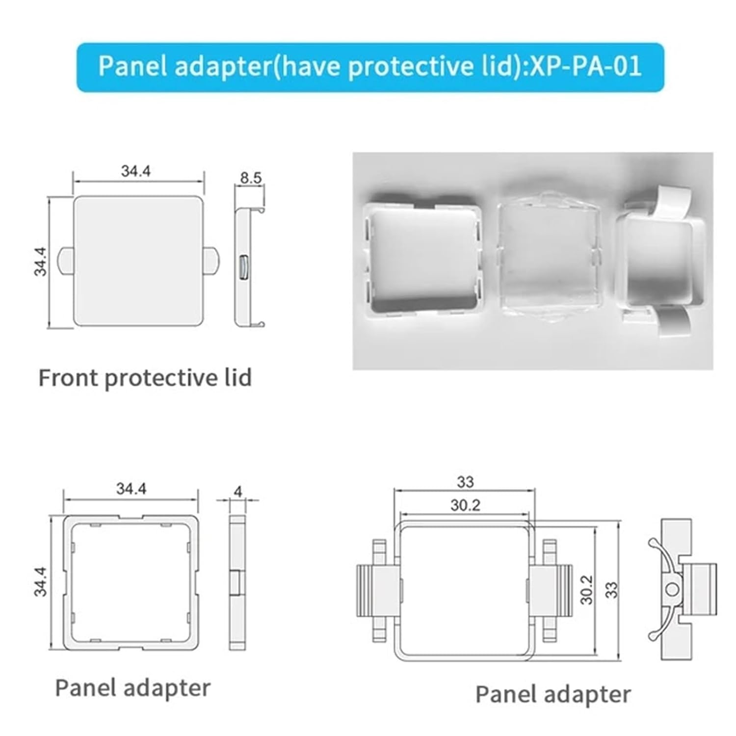
Image 4.1: Examples of how the pressure switch can be installed, showing connection to a 6mm air tube via an R1/8 thread.

Image 4.2: Technical drawings and views of the optional XP-PA-01 panel adapter, including its protective lid and dimensions for mounting.
5. Operation
Once installed and powered, the digital display will show the current pressure reading. The device typically features three buttons for operation: 'S' (Set/Mode), 'Up' (Increase/Navigate), and 'Down' (Decrease/Navigate).
- Power On: The display will illuminate and show the current pressure.
- Reading Pressure: The main display shows the real-time pressure value.
- Setting Parameters: Press the 'S' button to enter the setting mode. Use the 'Up' and 'Down' buttons to navigate through parameters and adjust values. Press 'S' again to confirm settings or move to the next parameter. Specific parameter settings (e.g., set points, hysteresis, unit selection) will vary; refer to the on-screen prompts.
- Output Status: The output status (e.g., OUT1) may be indicated by an LED or a segment on the display.
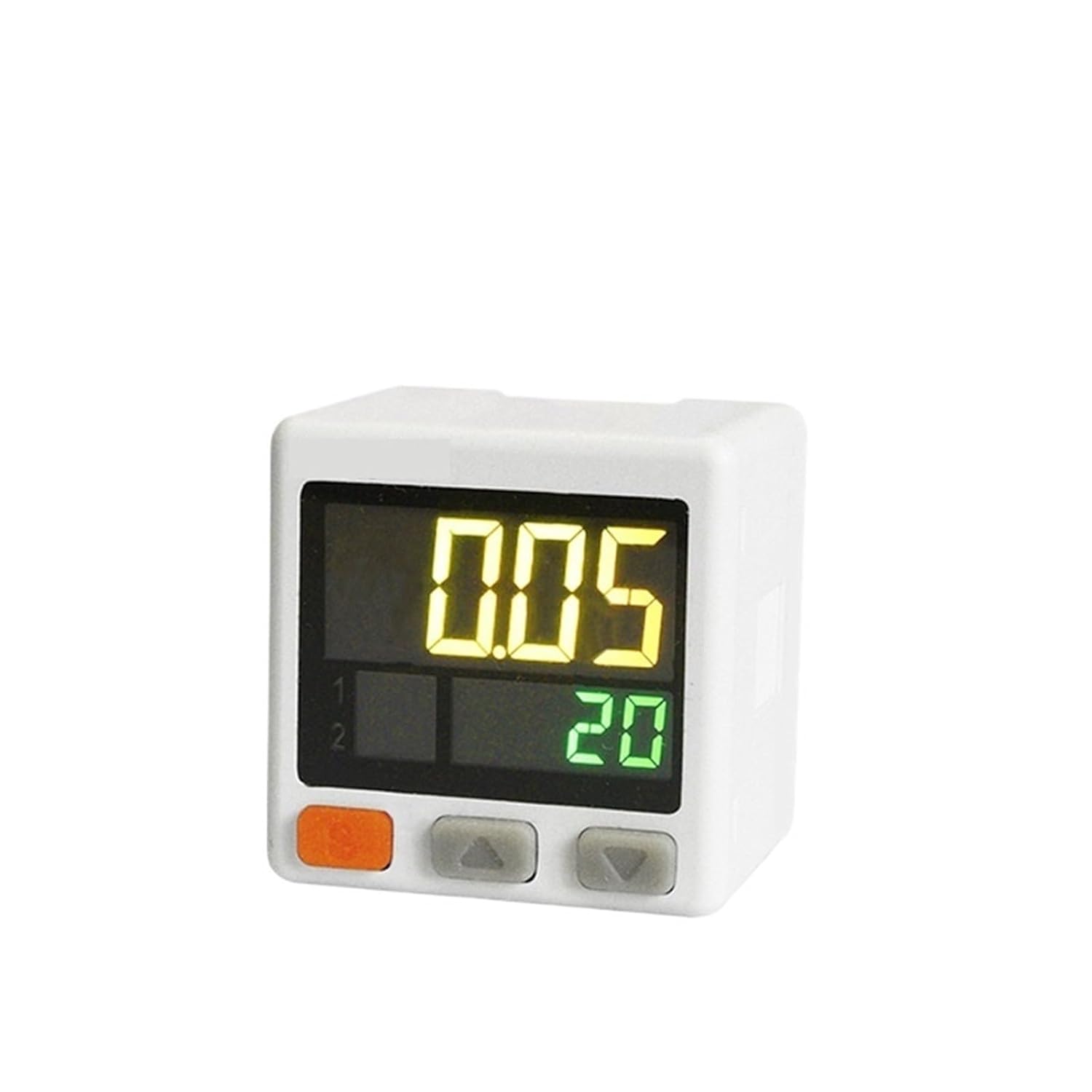
Image 5.1: A single HH8BWL digital pressure switch, highlighting its display and the 'S', 'Up', and 'Down' control buttons.
6. Specifications
The following table details the specifications for the HH8BWL MS30C001A Digital Display Pressure Switch:
| Feature | Specification |
|---|---|
| Model Number | MS30C001A |
| Rated Pressure Range | -101.3 ~ -101.3 kPa |
| Display Pressure Range | -101.3 ~ -101.3 kPa |
| Display/Minimum Unit Setting | 0.1 kPa |
| Withstand Pressure | 500 kPa |
| Port Size | R1/8 + M5 |
| Output Type | 1 NPN |
| Power Supply | DC 12-24V |
| Package Dimensions | 1.18 x 0.79 x 0.39 inches |
| Item Weight | 1.76 ounces |
| Manufacturer | HH8BWL |
Note: Specifications for other models (e.g., MS32C060A, MS32P060A) may differ, particularly regarding pressure ranges and communication interfaces (e.g., RS485). Always verify the model number for specific details.

Image 6.1: Reference image for model MS32C060A, showing its specifications and wiring diagram with 1 NPN and RS485 communication. This model is different from MS30C001A.

Image 6.2: Reference image for model MS32P060A, showing its specifications and wiring diagram with 1 NPN and RS485 communication. This model is different from MS30C001A.
7. Maintenance
The HH8BWL MS30C001A pressure switch is designed for minimal maintenance. Follow these guidelines to ensure longevity and accurate performance:
- Cleaning: Keep the device clean and free from dust and debris. Use a soft, dry cloth for cleaning the exterior. Do not use abrasive cleaners or solvents.
- Inspection: Periodically inspect the pressure connections and electrical wiring for any signs of wear, damage, or loose connections.
- Environmental Conditions: Ensure the operating environment remains within the specified temperature and humidity ranges.
8. Troubleshooting
If you encounter issues with your pressure switch, consider the following common troubleshooting steps:
- No Display/No Power:
- Check power supply connections (DC 12-24V).
- Verify the power source is active and providing the correct voltage.
- Incorrect Pressure Reading:
- Ensure the pressure port is securely connected and free of leaks.
- Verify the pressure source is stable and within the device's rated range.
- Check for any blockages in the pressure line.
- Output Not Activating:
- Confirm that the set points and hysteresis settings are correctly configured.
- Check the wiring of the NPN output to the connected load.
- Ensure the pressure is within the range that should trigger the output.
If problems persist after attempting these steps, contact customer support or a qualified technician.
9. Warranty and Support
For warranty information and technical support, please refer to the documentation provided at the time of purchase or contact your vendor directly. Keep your purchase receipt as proof of purchase.