1. Introduction
This manual provides detailed instructions for the installation, operation, and maintenance of the VGVGV SR208C WiFi Solar Water Heat Controller. The SR208C is designed to efficiently manage solar heating systems, offering precise temperature control and optional WiFi remote monitoring capabilities. It features innovative MPPT technology for high tracking efficiency, contributing to increased energy generation. The controller is built for durability with excellent heat dissipation.
2. Safety Information
- Ensure the power supply is disconnected before any installation or maintenance procedures.
- All electrical connections must be performed by a qualified electrician in accordance with local and national electrical codes.
- Do not expose the controller to direct moisture or extreme temperatures outside its specified operating range.
- Verify correct sensor polarity and connection points to prevent damage to the unit or inaccurate readings.
- Keep the device away from flammable materials.
3. Package Contents
Upon unpacking, please verify that all the following items are present:
- VGVGV SR208C Solar Water Heat Controller
- 1 x Pt1000 sensor (for collector temperature measurement)
- 2 x NTC10K, B3950 sensors (for tank temperature measurement)
- Instruction Manual
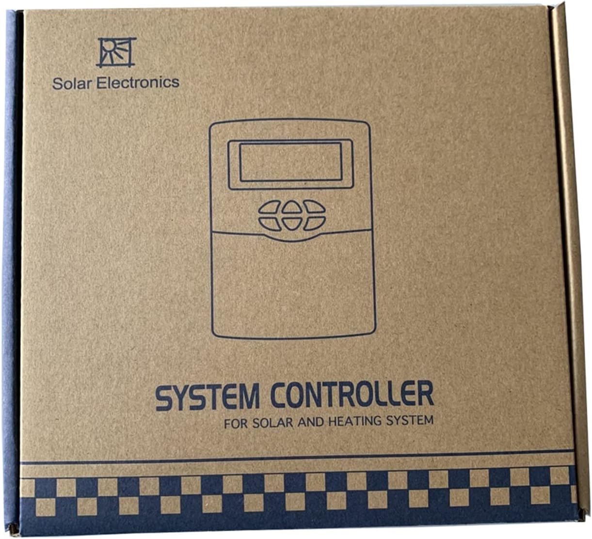
Image: The packaging box for the VGVGV SR208C Solar Water Heat Controller, indicating 'SYSTEM CONTROLLER FOR SOLAR AND HEATING SYSTEM'.
4. Product Overview
The SR208C controller features a clear display and intuitive buttons for easy operation. The front panel includes a display screen and control buttons for navigation and setting adjustments.
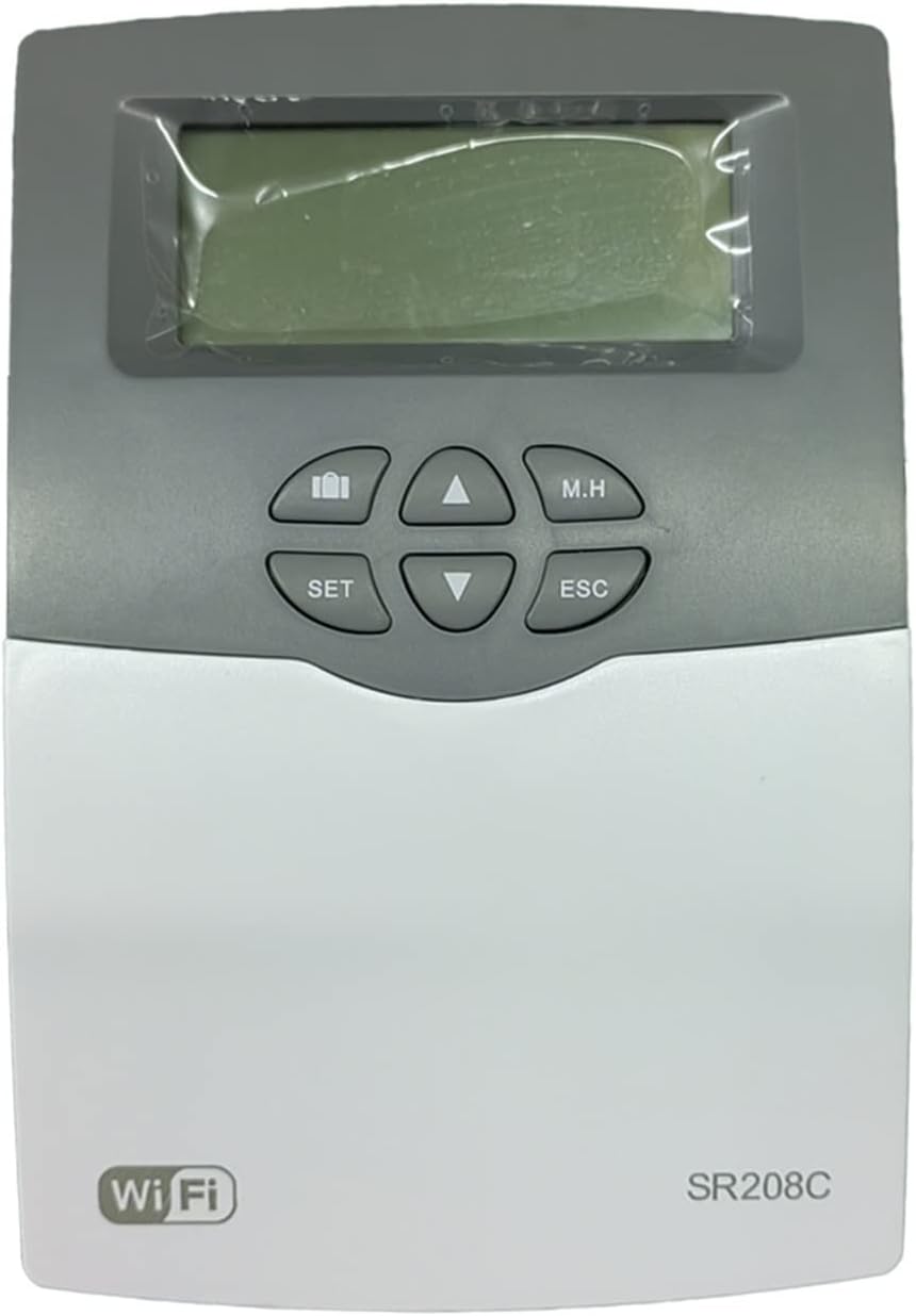
Image: Front view of the VGVGV SR208C controller, showing the LCD screen, 'SET', 'M.H', 'ESC' buttons, and up/down/left/right navigation buttons. The 'WiFi' logo and 'SR208C' model name are visible at the bottom.
Control Buttons:
- SET: Enters setting mode or confirms a selection.
- M.H (Manual Heating): Activates or deactivates manual heating function.
- ESC (Escape): Exits current menu or cancels an operation.
- Up/Down Arrows: Navigate through menu options or adjust values.
- Left/Right Arrows: Navigate through menu options or adjust values.
5. Setup
Follow these steps for proper installation and connection of the SR208C controller.
5.1 Mounting the Controller
Mount the controller in a dry, protected location, away from direct sunlight and moisture. Ensure adequate ventilation around the unit.
5.2 Electrical Connections
- Power Supply: Connect the AC100-240V, 50-60Hz power supply to the designated input terminals on the controller.
- Sensor Connections:
- Connect the Pt1000 sensor (silicon cable, rated for 500°C) to the collector sensor input. This sensor measures the temperature of the solar collector.
- Connect the two NTC10K, B3950 sensors (PVC cable, rated for 135°C) to the tank sensor inputs. These sensors measure the temperature within the storage tank.
- Output Connections:
- Connect the circulation pump to the designated relay output.
- Connect the backup heating element (if applicable, max 500W) to its respective relay output.

Image: The VGVGV SR208C controller displaying temperature readings, shown alongside three connected sensors (two NTC10K sensors with white cables and one Pt1000 sensor with a black cable).
5.3 Initial Power-Up
Once all connections are secure, apply power to the controller. The display should illuminate, showing current temperatures and system status.
5.4 WiFi Setup (Optional)
If your model includes WiFi functionality, refer to the separate WiFi module instructions for connecting the controller to your local network for remote monitoring and control.
6. Operating Instructions
The SR208C controller allows for monitoring and adjustment of your solar heating system parameters.
6.1 Display Information
The main display typically shows:
- Current time
- Collector temperature
- Tank temperature
- System status indicators (e.g., pump running, heating active)
6.2 Setting Parameters
- Press the SET button to enter the parameter setting mode.
- Use the Up/Down arrows to navigate through different parameters (e.g., desired tank temperature, differential temperature for pump activation, time settings).
- Press SET again to select a parameter for editing.
- Use the Up/Down arrows to adjust the value.
- Press SET to confirm the new value.
- Press ESC to exit the setting mode at any time without saving changes, or repeatedly press ESC to return to the main display after saving.
6.3 Manual Heating (M.H)
Press the M.H button to manually activate or deactivate the backup heating function. This can be useful for temporary heating needs or system testing. Ensure this function is used responsibly to avoid unnecessary energy consumption.
7. Maintenance
Regular maintenance ensures optimal performance and longevity of your SR208C controller.
- Cleaning: Periodically wipe the controller's exterior with a soft, dry cloth. Do not use abrasive cleaners or solvents.
- Sensor Check: Annually inspect sensor cables for any signs of damage or wear. Ensure sensors are securely in place and free from debris.
- Connection Check: Periodically check all electrical connections for tightness and corrosion.
- Software Updates: If WiFi functionality is used, check for available firmware updates to ensure the controller operates with the latest features and improvements.
8. Troubleshooting
Refer to the following table for common issues and their solutions.
| Problem | Possible Cause | Solution |
|---|---|---|
| Controller display is off | No power supply; Loose connection | Check power source and connections; Ensure power cable is securely plugged in. |
| Inaccurate temperature readings | Faulty sensor; Incorrect sensor connection; Sensor not properly installed | Verify sensor connections and polarity; Check sensor for physical damage; Ensure sensors are correctly positioned in collector/tank. |
| Pump not activating | Temperature differential not met; Pump malfunction; Controller settings incorrect | Check current collector and tank temperatures; Verify pump functionality; Review controller settings for pump activation thresholds. |
| WiFi connection issues | Incorrect network settings; Router issues; Signal interference | Re-enter WiFi credentials; Restart router; Ensure controller is within WiFi range. |
9. Specifications
| Parameter | Value |
|---|---|
| Controller Dimensions | 178mm x 120mm x 43mm (7.01"L x 4.72"W x 1.69"H) |
| Power Supply | AC100-240V, 50-60Hz |
| Power Consumption | < 2.5W |
| Temperature Measuring Accuracy | ± 0.1°C |
| Collector Temperature Range | -10°C ~ 220°C |
| Tank Temperature Range | 0°C ~ 110°C |
| Max. Number of Collectors | 1 |
| Max. Number of Storage Tanks | 1 |
| Max. Number of Relays | 2 |
| Max. Number of Sensors | 3 |
| Collector Sensor | 1 x Pt1000 (500°C, silicon cable 280°C) |
| Tank Sensors | 2 x NTC10K, B3950 (135°C, PVC cable 105°C) |
| Outputs | 2 relays (for circulation pump and backup heating) |
| Suitable Power of HK (backup heating) | 1pc 500W |
| Ambient Temperature | -10°C ~ 50°C |
| Water Proof Grade | IP41 |
| Material | Metal, Plastic |
| Item Weight | 0.353 ounces (10 Grams) |
| Display Type | LCD or LED |
10. Warranty and Support
For warranty information and technical support, please refer to the documentation provided with your purchase or contact VGVGV customer service. Keep your purchase receipt for warranty claims.