
1. Introduction
The Nasedal ET835PRO is a versatile 4-in-1 device designed for comprehensive network cable testing and maintenance. It integrates a network cable tester, optical power meter, Visual Fault Locator (VFL), and a digital multimeter. This tool is suitable for professionals involved in engineering wiring, network installation, and equipment maintenance, providing accurate and efficient diagnostics.
This manual provides detailed instructions on the device's functions, setup, operation, and maintenance to ensure optimal performance and longevity.
2. Product Overview
The Nasedal ET835PRO combines multiple testing capabilities into a single, portable unit. Key features include:
- Anti-interference Network Cable Testing: Utilizes a digital mode for accurate cable tracing with high sensitivity and reduced noise.
- Multifunctional Network Cable Tester: Features QC testing, length measurement, cable scan, cable mapping, POE voltage/polarity test, switch port flash, and ID mapping.
- 60000 Count Multimeter: Measures AC/DC voltage, AC/DC current, resistance, capacitance, frequency, diodes, and continuity.
- Optical Power Measurement: Tests optical signal power and attenuation with REF function.
- Visual Fault Locator (VFL): 10mW, 10KM range, with selectable frequencies (1Hz/2Hz/steady on).
- POE Test and Switch Flash: Checks POE voltage and polarity (up to 60VDC) and identifies network switch ports.
- Cable Length Test: Measures length for RJ45, phone, and coaxial cables up to 600m.
- Rechargeable Battery: Equipped with a 1500mAH (Host) / 800mAH (Receiver) lithium battery and Type-C charging.
- Integrated Flashlight: Assists in low-light working conditions.
2.1 Package Contents
The Nasedal ET835PRO package includes the following items:
- Nasedal ET835PRO Main Unit (Tester)
- Receiver Unit
- Remote Units (3 units)
- Multimeter Test Leads
- USB Type-C Charging Cable
- RJ45 Patch Cables
- Alligator Clip Cable
- User Manual
- Carrying Case

Figure 1: Nasedal ET835PRO main unit, receiver, remote units, test leads, and cables.
2.2 Device Components
Familiarize yourself with the main components of the ET835PRO tester and its receiver:

Figure 2: Detailed view of the ET835PRO main unit and receiver with labeled ports and buttons.
- Main Unit (Tester):
- LCD Color Screen: Displays test results and menu options.
- Keypad: Navigation and function selection.
- OPM Port: Optical Power Meter input.
- VFL Port: Visual Fault Locator output.
- USB Charging Port: Type-C for battery charging.
- TEST/SCAN/QC/ID Interface: For network cable testing.
- Port Flashing Interface: For connecting to network switches.
- POE Testing Interface: For Power over Ethernet tests.
- Multimeter Probe Sockets: For connecting test leads (10A MAX, COM, VΩHz).
- Receiver Unit:
- SCAN Button: Initiates cable scanning.
- NCV Button: Non-Contact Voltage detection.
- Sensitivity Modulation: Adjusts tracing sensitivity.
- Flashlight Switch: Activates the built-in flashlight.
- Functional LED: Indicates status.
- Tracing/NCV Sensor: Detects cable signals and voltage.
- RJ-45 Cable Jack: For connecting network cables.
- SCAN Verification Light: Indicates scan status.
3. Setup
3.1 Charging the Device
The ET835PRO main unit and receiver are equipped with rechargeable lithium batteries. Use the provided USB Type-C cable to charge both units. Connect the cable to the Type-C port on each device and to a standard USB power adapter (not included).
- Main Unit Battery: 1500mAH
- Receiver Unit Battery: 800mAH
A full charge ensures extended operation. The battery indicator on the screen will show charging status.
3.2 Language Settings
The device supports multiple languages. To change the language:
- Power on the main unit.
- Navigate to the SETUP menu using the navigation buttons.
- Select Language and choose your preferred language (e.g., English, Deutsch, French, Español).
- Confirm your selection.

Figure 3: Language selection interface on the ET835PRO.
3.3 Auto Power Off and Sound Settings
Within the SETUP menu, you can also configure:
- Auto power off: Set the inactivity duration before the device automatically powers off to conserve battery.
- Sound: Enable or disable audible feedback.
- LED light: Control the LED backlight.
4. Operating Instructions
4.1 Network Cable Testing (LENGTH, WIREMAP, SCAN, QC, ID)
The ET835PRO offers various functions for testing network cables (RJ45, CAT5, CAT6, CAT7, CAT8 UTP/STP).
4.1.1 Cable Length Measurement
This function measures the length of network, phone, and coaxial cables.
- Select LENGTH from the main menu.
- Connect one end of the cable to the main unit's TEST/SCAN/QC/ID interface.
- For accurate readings, ensure the other end of the cable is not connected to any active device.
- The device will display the cable length in meters or feet.
- Calibration: For precise length measurements, especially for different cable types, calibration is recommended. Connect a known length of cable (e.g., 5 meters) and follow the on-screen calibration prompts in the LENGTH menu.

Figure 4: Cable length measurement interface.
4.1.2 Wiremap Test
The Wiremap function checks the pin-to-pin configuration of network cables to detect open circuits, short circuits, cross-overs, and split pairs.
- Select WIREDMAP from the main menu.
- Connect one end of the network cable to the main unit's TEST/SCAN/QC/ID interface.
- Connect the other end of the cable to a remote unit (1, 2, or 3).
- The screen will display the wiring sequence and any detected faults.
4.1.3 Cable Scan (Wire Tracer/Toner)
This function helps locate a specific cable within a bundle or trace its path.
- Select SCAN from the main menu on the main unit.
- Connect the cable to be traced to the main unit's TEST/SCAN/QC/ID interface.
- Turn on the receiver unit and press its SCAN button.
- Move the receiver's tracing sensor along the cable bundle. The receiver will emit an audible tone, which will be strongest when near the target cable.
- Adjust the sensitivity on the receiver for optimal tracing.
4.1.4 QC Testing (Crimping Test)
The QC function verifies the quality of RJ45 crimps.
- Select QC from the main menu.
- Insert the crimped RJ45 connector into the main unit's TEST/SCAN/QC/ID interface.
- The device will analyze the crimp and indicate if it is properly made or if there are issues.
4.1.5 ID Mapping
This function helps identify network ports by connecting to remote units.
- Connect the main unit to a network cable.
- Connect remote units to different network ports at the other end.
- Select ID from the main menu. The device will display which remote unit is connected to the cable.
4.2 Optical Power Meter (OPM)
The OPM measures the power of optical signals and attenuation values.
- Select OPM from the main menu.
- Connect the optical fiber to the OPM port on the main unit. The device supports ST/SC/FC adapters.
- The screen will display the optical power in dBm, nW, and dB, along with the wavelength (e.g., 850nm, 980nm, 1300nm, 1310nm, 1490nm, 1550nm, 1625nm).
- Use the REF function to set a reference power level for attenuation measurements.

Figure 5: Optical Power Meter interface showing power levels and wavelengths.
4.3 Visual Fault Locator (VFL)
The VFL emits a visible red laser light into an optical fiber to locate breaks, bends, or poor connections.
- Select VFL from the main menu.
- Connect the optical fiber to the VFL port on the main unit.
- Choose the desired output mode: 1Hz (slow flash), 2Hz (fast flash), or steady on.
- Observe the fiber for red light leakage, indicating a fault. The VFL has a range of 10KM with 10mW output.

Figure 6: Visual Fault Locator in operation, showing red light emission.
4.4 Multimeter Function (DMM)
The integrated 60000 count multimeter allows for various electrical measurements.
- Select DMM from the main menu.
- Connect the multimeter test leads to the appropriate sockets (10A MAX, COM, VΩHz) on the main unit.
- Select the desired measurement mode (AC/DC voltage, AC/DC current, resistance, capacitance, frequency, diode test, continuity test) using the navigation buttons.
- Apply the test leads to the circuit or component to be measured. The reading will be displayed on the screen.
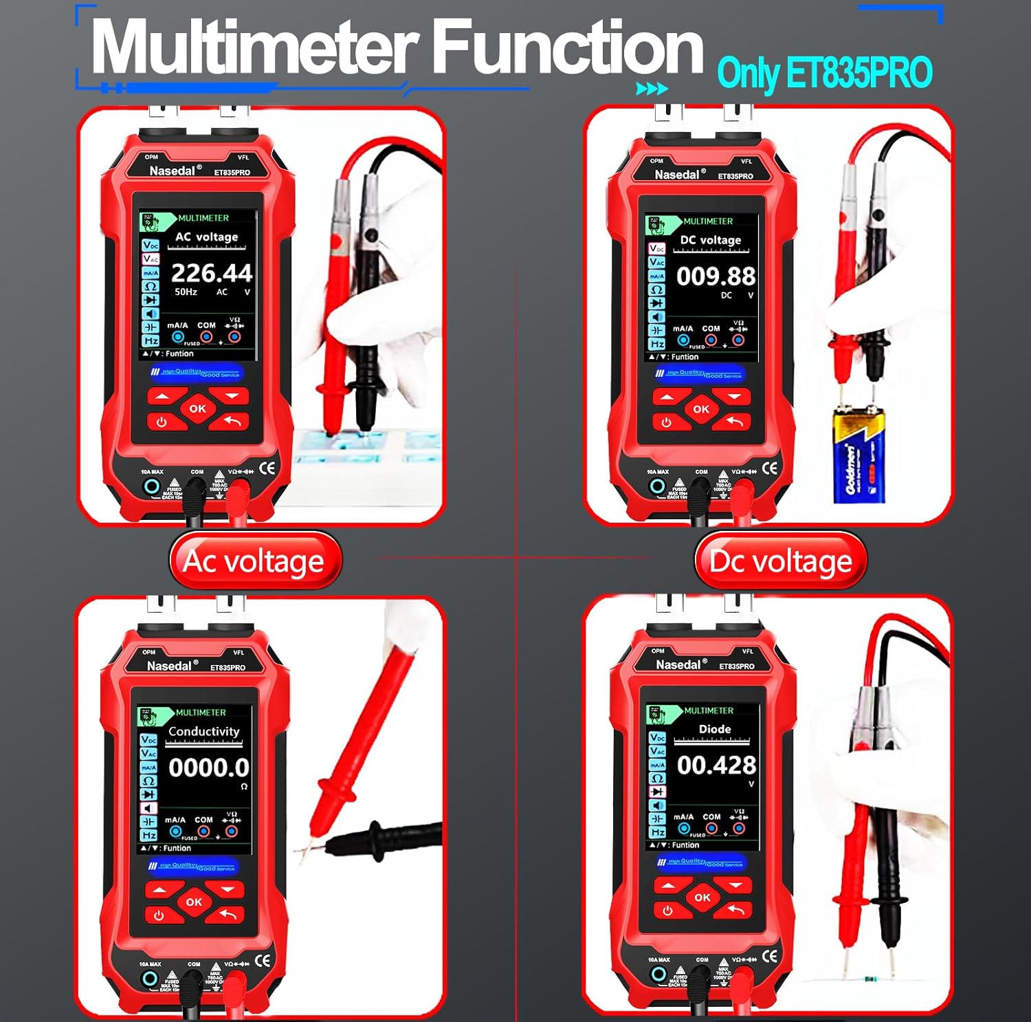
Figure 7: Multimeter functions including AC/DC voltage, conductivity, and diode testing.
4.5 POE Test and Switch Flash
These functions are used for Power over Ethernet (PoE) diagnostics and network switch port identification.
- POE Test:
- Select POE from the main menu.
- Connect the network cable from a PoE source to the POE testing interface on the main unit.
- The device will display the PoE voltage and polarity. It can withstand up to 60VDC.
- Switch Flash:
- Select FLASH from the main menu.
- Connect the main unit's Port Flashing Interface to a port on a network switch (10M/100M/1000M compatible).
- The device will cause the corresponding LED on the network switch to flash, helping to identify the specific port of the connected cable.
4.6 NCV Function (Non-Contact Voltage)
The receiver unit includes a Non-Contact Voltage (NCV) detection feature.
- Turn on the receiver unit.
- Press the NCV button on the receiver.
- Move the NCV sensor near an AC voltage source. The receiver will indicate the presence of voltage through an audible alert and/or LED indicator.
5. Maintenance
5.1 Cleaning
To maintain the device's performance and appearance:
- Wipe the exterior of the main unit and receiver with a soft, dry cloth.
- Do not use abrasive cleaners, solvents, or corrosive chemicals.
- Keep the optical ports clean and free of dust. Use specialized optical cleaning tools if necessary.
5.2 Storage
When not in use, store the ET835PRO and its accessories in the provided carrying case in a cool, dry place, away from direct sunlight and extreme temperatures.
5.3 Battery Care
To prolong battery life:
- Charge the device regularly, even if not in frequent use.
- Avoid fully discharging the battery for extended periods.
- If storing for a long time, charge the battery to approximately 50% before storage.
6. Troubleshooting
If you encounter issues with your Nasedal ET835PRO, refer to the following common troubleshooting steps:
| Problem | Possible Cause | Solution |
|---|---|---|
| Device does not power on. | Low or depleted battery. | Charge the device using the Type-C cable. |
| Inaccurate cable length measurement. | Cable not calibrated; other end of cable connected to active device. | Calibrate the device for the specific cable type. Ensure the cable is disconnected from all active devices during measurement. |
| No tone during cable scan. | Receiver sensitivity too low; cable not properly connected; main unit not in SCAN mode. | Increase receiver sensitivity. Ensure cable is securely connected. Verify main unit is in SCAN mode. |
| Screen display is garbled or unresponsive. | Temporary software glitch. | Power off the device, then power it back on. If the issue persists, perform a factory reset via the SETUP menu. |
| Multimeter readings are incorrect. | Incorrect function selected; test leads improperly connected; faulty test leads. | Ensure the correct measurement mode is selected. Verify test lead connections. Replace test leads if damaged. |
If the problem persists after attempting these solutions, please contact customer support.
7. Specifications
| Feature | Detail |
|---|---|
| Model Number | ET835PRO |
| Brand | Nasedal |
| Display | 3.2-inch Color LCD Screen |
| Cable Length Measurement Range | 5m ~ 600m (16ft ~ 1968ft) for RJ45; 400m for phone/coaxial cables |
| Optical Power Meter Range | -70 ~ +6dBm |
| VFL Output Power | 10mW (10KM range) |
| Multimeter Count | 60000 Counts |
| POE Test Voltage | Up to 60VDC |
| Main Unit Battery | 1500mAH Lithium (rechargeable) |
| Receiver Battery | 800mAH Lithium (rechargeable) |
| Charging Port | USB Type-C |
| Dimensions (Package) | 10.2 x 6.57 x 2.95 inches |
| Weight (Package) | 1.92 Pounds |
| Manufacturer | Shenzhen Anboll E-commerce Co. Ltd |
| Safety Standard | EN 61010-1 |
8. Warranty and Support
For warranty information and technical support, please refer to the documentation included with your purchase or contact the manufacturer directly. The manufacturer is Shenzhen Anboll E-commerce Co. Ltd.
Please retain your proof of purchase for any warranty claims.
