
1. Introduction
The GOOZEEZOO JPC-350 is a portable HF vertical antenna designed for amateur radio enthusiasts. It covers 80m, 40m, 20m, 17m, 15m, 12m, 10m, and 6m bands, offering frequency flexibility for various communication needs. This antenna supports a 100W SSB power rating and is engineered for superior reception and reliable signal transmission, making it suitable for portable operations like POTA (Parks On The Air) and SOTA (Summits On The Air), as well as emergency communications.
Its lightweight design (1.5KG) and modular structure allow for rapid deployment, typically within 5 minutes. The JPC-350 features a sliding contact inductive coil for precision tuning and includes a stainless steel telescoping rod for fine-tuned frequency adjustments, aiming for a Standing Wave Ratio (SWR) of 1.5 or lower.
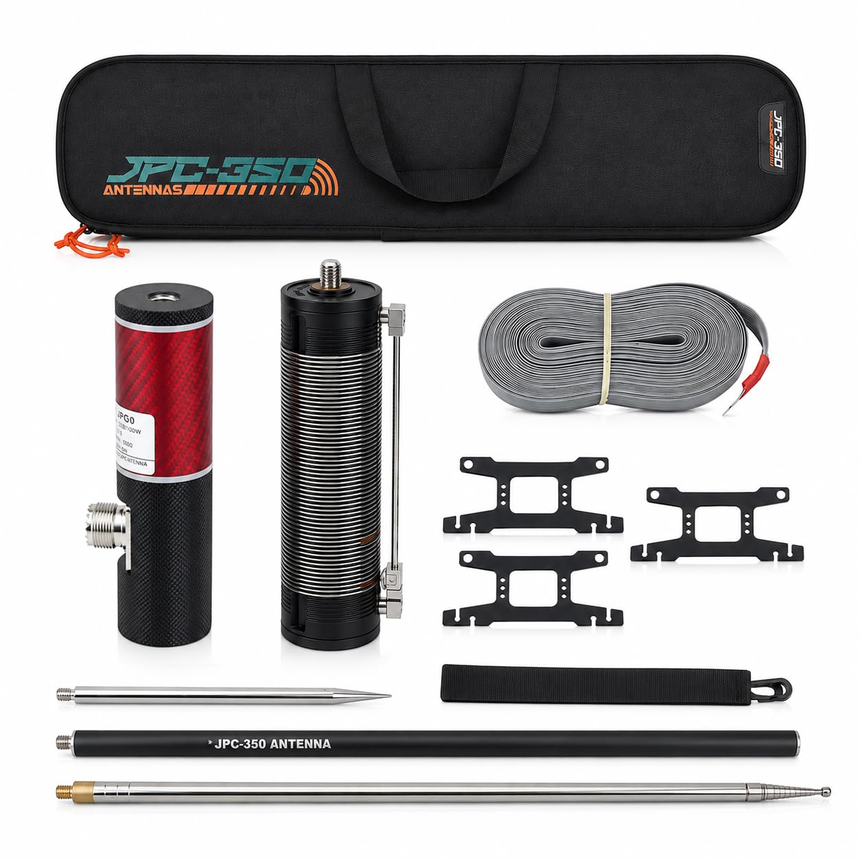
Image 1.1: The GOOZEEZOO JPC-350 Portable HF Vertical Antenna fully assembled and deployed in an open field, demonstrating its vertical orientation and compact footprint.
2. Components Overview
The JPC-350 antenna system includes several key components designed for easy assembly and portability. Familiarize yourself with these parts before proceeding with installation.

Image 2.1: A visual breakdown of the JPC-350 antenna system components, including the grounding grid wiring, ground anchor, aluminum tube, and telescopic antenna.
- Inductive Coil: The main tuning unit, featuring a sliding contact for band selection.
- Aluminum Alloy Base: Provides the primary connection point for the antenna and ground system.
- Aluminum Tubes: Sectional tubes that form the lower mast of the antenna.
- Telescopic Antenna Rod: The extendable upper radiating element for fine-tuning.
- Ground Anchor: A stake for securing the antenna base to the ground.
- Grounding Grid Wiring: Multiple strands of wire to establish an effective ground plane.
- Storage Bag: For convenient transport and protection of all components.
3. Setup Instructions
Follow these steps for quick and proper assembly of your JPC-350 antenna.
- Select an Installation Site: Choose a location free of physical obstructions and away from strong electromagnetic interference sources, such as high-voltage power lines.
- Assemble the Base:
- Insert the Ground Anchor into the ground at your chosen site.
- Attach the Ground Net (grounding grid wiring) to the Ground Anchor and spread the three ground radial wires outward at approximately 120-degree intervals.
- Connect the Aluminum Alloy Base to the Ground Anchor.
- Attach Aluminum Tubes: Connect the Aluminum Tubes to the Aluminum Alloy Base, forming the lower section of the antenna mast.
- Install Inductive Coil: Secure the Inductive Coil onto the top of the assembled Aluminum Tubes.
- Mount Telescopic Antenna: Insert the Stainless Steel Telescoping Rod Antenna into the top of the Inductive Coil. Extend the rod as needed for initial tuning.

Image 3.1: Visual guide for the JPC-350 antenna installation, showing the sequence of components and a deployed antenna with ground radials.
Video 3.1: An official video demonstrating the assembly process of the GOOZEEZOO JPC-350 HF Vertical Antenna. This video provides a visual guide to setting up the antenna components.
4. Operating Instructions
Achieving optimal performance with your JPC-350 antenna requires careful tuning for your desired operating frequency.
4.1 Band Selection and Tuning
The inductive coil features a sliding contact mechanism for selecting the operating band. The manual provides clear, color-coded marking areas (Red/Gold/White) to assist in quickly finding the correct settings for each band.

Image 4.1: A detailed view of the JPC-350 inductive coil, illustrating the sliding contact for band selection and the marked areas for 80m, 40m, and 20-12m bands.
- Initial Setting: Refer to the markings on the inductive coil for the approximate position for your desired band (80m, 40m, 20m, 17m, 15m, 12m, 10m, 6m).
- Fine-Tuning: Use an SWR meter to measure the Standing Wave Ratio. Adjust the sliding contact on the inductive coil and extend/retract the stainless steel telescoping rod to achieve an SWR of 1.5 or lower. Small adjustments can significantly impact SWR.
- Optimal Performance: Aim for the lowest possible SWR for efficient power transfer and best signal quality.
4.2 Safety Guidelines
Adhere to the following safety guidelines during operation:
- Avoid operating the antenna during thunderstorms or in environments with strong electromagnetic fields to prevent lightning strikes or interference.
- Ensure all connections are secure and stable before and during operation.
- Always comply with local laws and regulations regarding amateur radio operation and frequency usage.
5. Maintenance
Proper maintenance ensures the longevity and reliable performance of your JPC-350 antenna.
- Regular Inspection: Periodically inspect all components, especially connections and mounting points, for any signs of wear, corrosion, or damage.
- Cleaning: Clean the antenna components with a soft, dry cloth. Avoid using abrasive cleaners or solvents that could damage the materials.
- Storage: When not in use, disassemble the antenna and store it in the provided storage bag in a dry, protected environment to prevent damage from weather or physical impact.
- Handling: Avoid impact or excessive pulling on the antenna during installation, operation, and disassembly to protect its structural integrity.

Image 5.1: The JPC-350 antenna components organized within its storage bag, highlighting its portability and ease of storage.
6. Troubleshooting
This section addresses common issues you might encounter with your JPC-350 antenna.
| Problem | Possible Cause | Solution |
|---|---|---|
| High SWR (Standing Wave Ratio) |
|
|
| Poor Signal Reception/Transmission |
|
|
| Physical Instability |
|
|
7. Specifications
Detailed technical specifications for the GOOZEEZOO JPC-350 Portable HF Vertical Antenna.
| Feature | Specification |
|---|---|
| Model Number | JPC-350 |
| Brand | GOOZEEZOO |
| Frequency Bands | 80m, 40m, 20m, 17m, 15m, 12m, 10m, 6m (7MHz-50MHz) |
| Power Rating | 100W SSB |
| SWR | ≤1.5 |
| Impedance | 50 ohm |
| Weight | 1.5 KG (3.3 lbs) |
| Product Dimensions (Packed) | 23.6"L x 7.1"W x 3.2"H |
| Construction Materials | Aluminum alloy, stainless steel |

Image 7.1: A comparison table highlighting the specifications of the JPC-350 alongside previous models (JPC-12, JPC-7), detailing frequency bands, power, impedance, and weight.
8. Warranty Information
The GOOZEEZOO JPC-350 Portable HF Vertical Antenna comes with a 1-year manufacturer's warranty from the date of purchase. This warranty covers defects in materials and workmanship under normal use.
Please retain your proof of purchase for any warranty claims. The warranty does not cover damage caused by misuse, accidents, unauthorized modifications, or natural disasters.
9. Customer Support
For any questions, technical assistance, or support regarding your GOOZEEZOO JPC-350 antenna, please contact our customer service team. We are committed to providing prompt and satisfactory support.
- Response Time: Expect a quick response to your inquiries.
- Customer Satisfaction: Our goal is 100% customer satisfaction.
Please refer to the contact information provided with your product packaging or visit the official GOOZEEZOO website for the most up-to-date support details.