1. Introduction
This manual provides detailed instructions for the installation, operation, and maintenance of the AV Access 4K HDMI USB KVM Extender Bundle. This bundle includes two distinct KVM extender models: the 4KIP100-KVM, which utilizes Cat5e/6/6a/7 Ethernet cables for extension up to 390ft (120m), and the 4KIP500F-KVM, which uses fiber optic cables for extension up to 1800ft (550m). Both models enable the extension of 4K HDMI video and USB keyboard/mouse signals over long distances, offering flexible solutions for various environments.
2. Product Features
- High Refresh Rate: Supports 4K@30Hz and 1080P@120Hz video transmission.
- USB 2.0 Hub: Each receiver unit includes a 3-port USB 2.0 hub for connecting keyboard, mouse, and other USB devices.
- DIP Switch Configuration: Allows for pairing of up to 16 sets of extenders within the same network.
- Zero Latency: Designed for real-time control with minimal signal delay.
- Audio Support: Supports 7.1-channel audio.
- Plug & Play: No driver installation required for basic operation.
- Electromagnetic Interference (EMI) Immunity (4KIP500F-KVM): Fiber optic connection provides optical isolation, ensuring stable video transmission in environments with high EMI.
3. Setup and Connection
This section details the setup procedures for both KVM extender models. Ensure all devices are powered off before making connections.
3.1. 4KIP100-KVM (Cat5e/6/6a/7 Extender)
This model extends HDMI and USB signals over a single Cat5e/6/6a/7 Ethernet cable up to 390ft (120m).

Image 3.1.1: Front and rear views of the 4KIP100-KVM Transmitter (top) and Receiver (bottom) units, showing ports and DIP switches.
3.1.1. One-to-One Connection
- Connect the HDMI output of your source device (e.g., PC) to the HDMI In port on the 4KIP100-KVM Transmitter (TX).
- Connect a USB cable from your source device to the USB Host port on the TX unit.
- Connect an Ethernet cable (Cat5e/6/6a/7) from the LAN port on the TX unit to the LAN port on the 4KIP100-KVM Receiver (RX).
- Connect the HDMI Out port on the RX unit to the HDMI input of your display.
- Connect your USB keyboard, mouse, or other USB devices to the USB Device ports on the RX unit.
- Ensure the DIP switches on both the TX and RX units are set to the same channel ID for proper pairing.
- Connect the 12V DC power adapters to both the TX and RX units and power them on.

Image 3.1.2: Diagram illustrating a direct one-to-one connection between a PC, 4KIP100-KVM Transmitter, Receiver, and display/peripherals.
3.1.2. Network Deployment (Up to 16 Sets)
For deploying multiple KVM extender sets within the same network, an Ethernet switch is required. Each Transmitter (TX) must be paired with a single Receiver (RX) using the DIP switches.
- Connect the LAN port of each TX unit to an Ethernet switch.
- Connect the LAN port of each RX unit to the same Ethernet switch.
- For each TX-RX pair, set the 4-pin DIP switches on both units to an identical, unique channel ID. Up to 16 unique channel IDs are available.
- Connect HDMI and USB cables to the TX and RX units as described in the one-to-one connection.
- Power on all TX and RX units after configuring DIP switches.
Note: One TX can only be paired with one RX. Repower TX and RX units for DIP switch changes to take effect. This setup does not support matrix switching with a Gigabit switch.
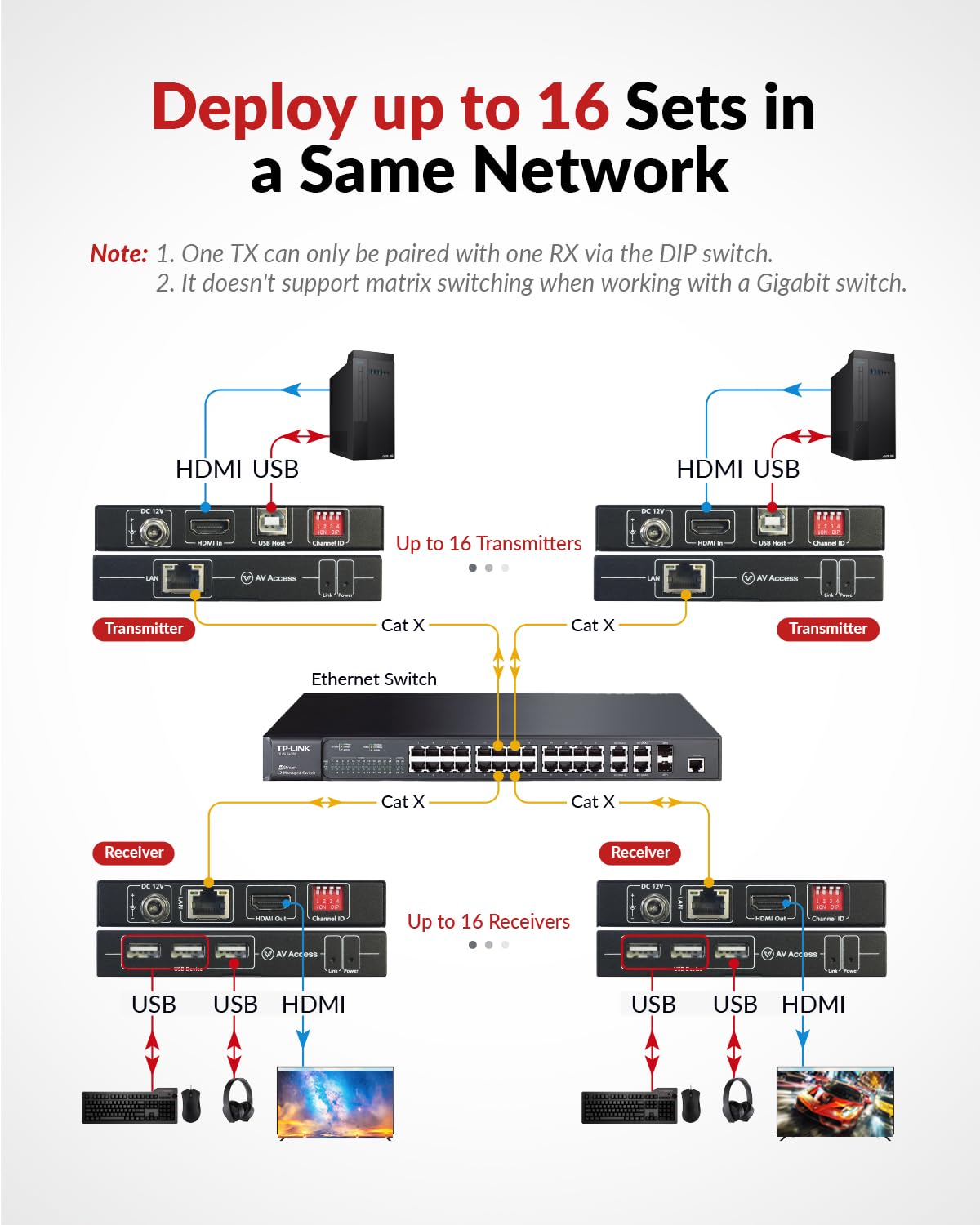
Image 3.1.3: Diagram showing how to deploy multiple 4KIP100-KVM extender sets using an Ethernet switch, with each TX and RX pair configured via DIP switches.
3.2. 4KIP500F-KVM (Fiber Optic Extender)
This model extends HDMI and USB signals over a multi-mode fiber optic cable up to 1800ft (550m).

Image 3.2.1: Front and rear views of the 4KIP500F-KVM Transmitter (top) and Receiver (bottom) units, highlighting optical ports and DIP switches.
3.2.1. One-to-One Connection
- Connect the HDMI output of your source device (e.g., PC) to the HDMI In port on the 4KIP500F-KVM Transmitter (TX).
- Connect a USB cable from your source device to the USB Host port on the TX unit.
- Connect a multi-mode fiber optic cable from the Optical Out port on the TX unit to the Optical In port on the 4KIP500F-KVM Receiver (RX).
- Connect the HDMI Out port on the RX unit to the HDMI input of your display.
- Connect your USB keyboard, mouse, or other USB devices to the USB Device ports on the RX unit.
- Ensure the DIP switches on both the TX and RX units are set to the same channel ID for proper pairing.
- Connect the 12V DC power adapters to both the TX and RX units and power them on.

Image 3.2.2: Diagram illustrating a direct one-to-one connection between a PC, 4KIP500F-KVM Transmitter, Receiver, and display/peripherals using a fiber optic cable.
3.2.2. Network Deployment (Up to 16 Sets)
Similar to the Cat5e/6/6a/7 model, multiple fiber optic KVM extender sets can be deployed using an Ethernet switch. Each Transmitter (TX) must be paired with a single Receiver (RX) using the DIP switches.
- Connect the Optical Out port of each TX unit to an Ethernet switch via appropriate fiber optic transceivers (not included, if needed).
- Connect the Optical In port of each RX unit to the same Ethernet switch.
- For each TX-RX pair, set the 4-pin DIP switches on both units to an identical, unique channel ID. Up to 16 unique channel IDs are available.
- Connect HDMI and USB cables to the TX and RX units as described in the one-to-one connection.
- Power on all TX and RX units after configuring DIP switches.
Note: One TX only can be paired with one RX. Repower TX and RX units for DIP switch changes to take effect.

Image 3.2.3: Diagram showing how to deploy multiple 4KIP500F-KVM extender sets using an Ethernet switch, with each TX and RX pair configured via DIP switches and fiber optic cables.
3.2.3. Interface Overview (4KIP500F-KVM)

Image 3.2.4: Detailed diagram of the 4KIP500F-KVM Receiver (top) and Transmitter (bottom) interfaces, labeling DC12V Power Port, Optical In/Out, HDMI In/Out, USB Host/Device ports, Link LED Indicator, Power LED Indicator, and DIP Switch for Pairing.
4. Operating Instructions
Once the KVM extenders are properly connected and powered on, they should operate automatically. The Link LED indicator on both the TX and RX units will illuminate when a stable connection is established.
- Power On Sequence: It is recommended to power on the source device (PC) first, then the KVM extender TX unit, followed by the RX unit, and finally the display.
- USB Device Connection: Connect your USB keyboard, mouse, or other peripherals to the USB Device ports on the RX unit. These devices will function as if directly connected to the source PC.
- DIP Switch Pairing: If you need to change the pairing between a TX and RX unit, ensure both units are powered off, adjust the DIP switches to the desired matching channel ID, and then power them back on.
5. Maintenance
To ensure optimal performance and longevity of your AV Access KVM extenders, follow these maintenance guidelines:
- Cleaning: Use a soft, dry cloth to clean the exterior of the units. Do not use liquid or aerosol cleaners.
- Ventilation: Ensure proper airflow around the units to prevent overheating. Do not block ventilation openings.
- Cable Management: Keep cables neatly organized and avoid sharp bends or excessive tension, especially for fiber optic cables.
- Power Supply: Use only the provided power adapters. Do not use damaged power cords or adapters.
6. Troubleshooting
If you encounter issues with your KVM extender bundle, refer to the following troubleshooting steps:
| Problem | Possible Cause | Solution |
|---|---|---|
| No video output | Loose HDMI/Ethernet/Fiber cable; Incorrect DIP switch setting; Power issue; Incompatible resolution. | Check all cable connections; Ensure TX and RX DIP switches match; Verify both units are powered on; Try a lower resolution on the source device. |
| USB devices not working | Loose USB cable; Power issue; USB device incompatibility. | Ensure USB cables are securely connected; Verify both units are powered on; Test with a different USB device; Some high-power USB devices may require external power. |
| Intermittent signal/Flickering video | Poor quality/damaged cable; Excessive cable length; Electromagnetic interference (for Cat5e/6/6a/7 model). | Replace cables with high-quality, certified ones; Ensure cable length is within specified limits (390ft for Cat, 1800ft for Fiber); For Cat model, ensure cables are away from strong electrical sources. |
| DIP switch changes not taking effect | Units not repowered after change. | Always power cycle both the TX and RX units after making any changes to the DIP switch settings. |
7. Specifications
Below are the general specifications for the AV Access 4K HDMI USB KVM Extender Bundle. Specific details may vary slightly between the 4KIP100-KVM and 4KIP500F-KVM models as noted.
| Feature | Description |
|---|---|
| Video Resolution | Up to 4K@30Hz, 1080P@120Hz |
| Audio Support | 7.1-channel audio |
| USB Ports | 1x USB Host (TX), 3x USB Device (RX) - USB 2.0, up to 480Mbps |
| Connectivity Protocol | TCP/IP |
| DIP Switch | 4-pin, supports up to 16 sets |
| Power Supply | DC 12V (included) |
| Operation Mode | Automatic |
| Color | Black |
| 4KIP100-KVM (Cat Extender) | |
| Transmission Medium | Single Cat5e/6/6a/7 Ethernet cable |
| Transmission Distance | Up to 390ft (120m) |
| 4KIP500F-KVM (Fiber Extender) | |
| Transmission Medium | Multi-mode Fiber Optic cable |
| Transmission Distance | Up to 1800ft (550m) |
8. Warranty and Support
AV Access products are designed for reliability and performance. For warranty information, technical support, or service inquiries, please refer to the official AV Access website or contact their customer support directly. Please have your product model number (4KIP100-KVM or 4KIP500F-KVM) and purchase details ready when contacting support.


