1. Introduction
This manual provides essential instructions for the installation, operation, and maintenance of your silkight 53.15" Biometric Wall Safe. Please read this manual thoroughly before installation and use to ensure proper function and safety. Keep this manual for future reference.
2. Safety Information
- Always store the emergency keys and emergency battery box in a secure location away from the safe and out of reach of unauthorized individuals.
- Do not store the emergency keys inside the safe.
- Ensure the safe is securely mounted to prevent unauthorized removal or tampering.
- Keep the keypad clean and dry to ensure proper functionality of the biometric and digital lock.
- Test the alarm system periodically to ensure it is functioning correctly.
- Replace batteries promptly when the low battery indicator appears to avoid being locked out.
3. Package Contents
Verify that all components are present before beginning installation.
- 1 x silkight Wall Gun Safe
- 3 x Removable Shelves
- 1 x Magnetic Gun Support
- 2 x Emergency Keys
- 1 x Emergency Battery Box
- 1 x Instruction Manual (this document)
- 8 x Expansion Screws
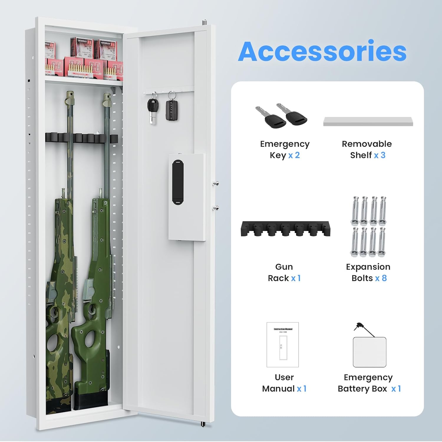
Figure 3.1: Included Accessories
This image displays the silkight wall safe and all its accompanying accessories, including emergency keys, removable shelves, a magnetic gun support, expansion screws, the user manual, and an emergency battery box.
4. Product Overview
The silkight 53.15" Biometric Wall Safe is designed for secure storage of valuables, firearms, and important documents. It features multiple unlocking methods and robust security features.
4.1 Key Features
- Robust Construction: Made from reinforced solid thickened cold alloy steel with 4 solid locking bolts on three sides for enhanced security.
- Hidden Design: Designed to fit between standard 16-inch on-center wall studs for discreet placement.
- Versatile Storage: Includes three adjustable shelves and a magnetic gun support, allowing customization for various items including rifles, pistols, documents, and jewelry.
- Dual Alarm System: Activates a 70-decibel alarm after 3 incorrect password attempts, 5 incorrect fingerprint attempts, or violent vibrations.
- Backlit Keypad & LED Light: Ensures visibility and ease of operation in low-light conditions. An internal LED light illuminates automatically upon opening.
- Mute Mode: Allows silent operation of the safe, preventing disturbance.
- Multiple Unlocking Methods: Fingerprint, Digital Code, Emergency Key, and Emergency Battery Box with Digital Code.

Figure 4.1: Open View of the Wall Safe
This image shows the silkight 53.15 inch biometric wall safe with its door open, revealing the internal storage compartments, adjustable shelves, and the biometric keypad on the exterior.

Figure 4.2: Hidden Wall Safe Features
This diagram illustrates the key features of the hidden wall safe, including its dual alarm system, mute mode, backlit keypad, removable shelves, gun support, LED light, password functionality, and key hooks.
4.2 Components
- Biometric Fingerprint Sensor: For quick and secure access.
- Digital Keypad: For code entry.
- Hidden Pop-up Knob: Used to open the safe after successful authentication.
- Emergency Keyhole: For manual override.
- Emergency Battery Box Port: For external power in case of dead internal batteries.
- Internal LED Light: Illuminates the safe's interior.
- Adjustable Shelves: For organizing contents.
- Magnetic Gun Support: For securing firearms.
- Key Hooks: Located on the inside of the door for small items.

Figure 4.3: Hidden Pop-up Knob and Keypad
This close-up image details the safe's hidden pop-up knob and the touch screen digital keypad, highlighting its backlit feature and the option to turn on/off the mute function.
5. Setup and Installation
Proper installation is crucial for the security and functionality of your wall safe. This safe is designed to fit between standard 16-inch on-center wall studs.
5.1 Site Selection
- Choose a location between two wall studs that are approximately 16 inches apart (center to center).
- Ensure there are no electrical wires, plumbing, or other obstructions within the wall cavity at the chosen location.
- Consider accessibility and discretion when selecting the installation spot (e.g., behind a mirror, painting, or inside a closet).

Figure 5.1: Example Installation Locations
This image displays various discreet installation locations for the wall safe, including inside a wardrobe, in a living room, bedroom, and office, demonstrating its versatility.
5.2 Installation Steps
- Locate Studs: Use a stud finder to accurately locate the center of two adjacent wall studs. Mark the outline of the safe's cabinet (H51.18" x W13.78" x D4.13") on the wall.
- Cut Opening: Carefully cut out the marked section of the drywall. Ensure the opening is precise to allow the safe to fit snugly.
- Insert Safe: Slide the safe into the wall opening. The front flange of the safe should rest flush against the wall surface.
- Secure Safe: Use the provided expansion screws to secure the safe to the wall studs through the pre-drilled holes inside the safe. Tighten all screws firmly.
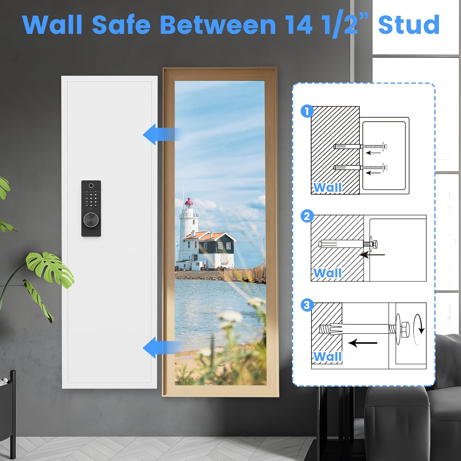
Figure 5.2: Wall Safe Installation Diagram
This diagram illustrates the three steps for installing the wall safe between studs: marking the wall, inserting the safe, and securing it with expansion screws.

Figure 5.3: Hidden Wall Safe Installation
This image shows the installation process of the hidden wall safe, demonstrating how it is secured with expansion screws and an example of it being concealed behind a mirror.
5.3 Initial Setup
- Install Batteries: Open the battery compartment (usually located on the inside of the door or behind the keypad) and insert 4 AA batteries (not included), ensuring correct polarity.
- First Opening: Use one of the emergency keys to open the safe for the first time. Insert the key into the emergency keyhole and turn it while rotating the handle.
- Set Master Code: With the door open, press the reset button (usually a small button inside the safe). Enter your desired master code (3-12 digits) on the keypad, then press '#' or 'ENTER'. Repeat to confirm.
- Register Fingerprints: With the door open, press the fingerprint registration button (refer to specific location in the manual). Place your finger on the sensor, lift, and repeat several times until registration is complete. You can register multiple fingerprints.
6. Operating Instructions
6.1 Unlocking Methods
Your safe offers four primary methods for unlocking:
- Fingerprint + Handle: Place a registered finger on the biometric sensor. Once recognized, rotate the pop-up knob to open the safe.
- Code + Handle: Enter your digital code on the keypad, then press '#' or 'ENTER'. Once accepted, rotate the pop-up knob to open the safe.
- Emergency Key + Handle: In case of forgotten code or dead batteries, insert the emergency key into the keyhole, turn it, and simultaneously rotate the handle to open.
- Emergency Battery Box + Code + Handle: If internal batteries are depleted and you don't have the emergency key, connect the emergency battery box to the external power port. Enter your digital code, then rotate the handle.

Figure 6.1: Fingerprint Unlock
This image illustrates the fingerprint unlock method for the safe, showing a finger being placed on the biometric sensor.

Figure 6.2: Password Unlock
This image illustrates the password unlock method for the safe, showing a hand entering a code on the digital keypad.

Figure 6.3: Key Unlock
This image illustrates the key unlock method for the safe, showing an emergency key inserted into the keyhole.

Figure 6.4: Emergency Battery Box Unlock
This image illustrates the emergency battery box unlock method for the safe, showing the external battery box connected to the keypad.
6.2 Dual Alarm System
The safe is equipped with a dual alarm system to deter unauthorized access:
- The alarm activates after 3 consecutive incorrect password entries or 5 incorrect fingerprint attempts.
- The alarm also activates if the safe experiences violent vibrations or tampering.
- The alarm emits a 70-decibel sound for 60 seconds.
- To stop the alarm, enter the correct password or use a registered fingerprint.
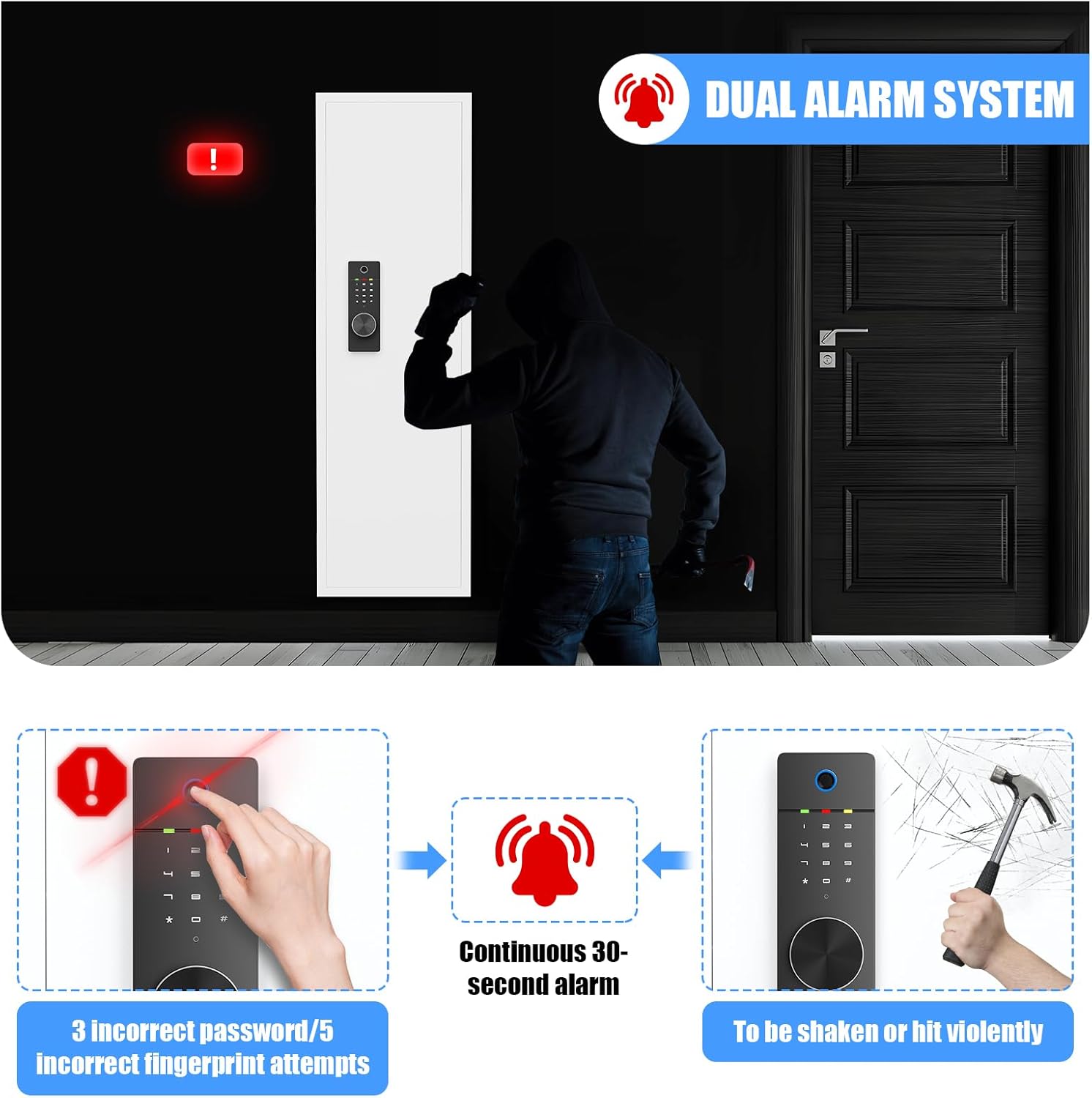
Figure 6.5: Dual Alarm System Activation
This diagram illustrates how the dual alarm system activates, either after 3 incorrect password attempts, 5 incorrect fingerprint attempts, or if the safe is violently shaken or hit, triggering a continuous 30-second alarm.

Figure 6.6: Alarm Sound Coverage
This diagram illustrates a house layout with a wall safe, showing red alarm circles emanating from it, indicating that the 70 DB alarm sound is audible throughout the entire home.
6.3 Mute Mode
To operate the safe without sound, activate the mute mode. Refer to the specific instructions in your detailed manual for enabling/disabling this feature. This is useful for discreet access without disturbing others.

Figure 6.7: Mute Mode Benefit
This image shows a person sleeping peacefully, illustrating the benefit of the safe's mute mode for silent operation.
6.4 Internal LED Light
The internal LED light automatically illuminates when the safe door is opened, providing visibility to the contents, especially in dark environments.

Figure 6.8: Internal LED Light
This image highlights the internal LED light strip within the safe, demonstrating how it illuminates the contents for easy access in dark environments.
7. Maintenance
7.1 Battery Replacement
When the low battery indicator light appears on the keypad, replace all 4 AA batteries promptly. Use only new, high-quality alkaline batteries. Do not mix old and new batteries or different battery types.
7.2 Cleaning
Clean the exterior of the safe and the keypad with a soft, dry cloth. Do not use abrasive cleaners or solvents, as these can damage the finish or electronic components.
7.3 Shelf and Gun Support Adjustment
The shelves are adjustable and removable. To adjust, simply lift and reposition them into the desired slots. The magnetic gun support can be moved as needed to accommodate different firearm sizes or configurations.

Figure 7.1: Removable Shelves and Rack
This image demonstrates the versatility of the safe's removable shelves and gun rack, allowing for various convenient storage configurations to suit different needs.
8. Troubleshooting
| Problem | Possible Cause | Solution |
|---|---|---|
| Safe does not open with code/fingerprint. | Incorrect code/fingerprint, dead batteries, keypad malfunction. | Ensure correct code/fingerprint. Replace batteries. Use emergency key or emergency battery box. |
| Alarm sounds unexpectedly. | Incorrect entries, tampering, low battery. | Enter correct code/fingerprint to disarm. Check for tampering. Replace batteries. |
| Keypad is unresponsive. | Dead batteries, connection issue. | Replace batteries. Use emergency battery box. If issue persists, contact customer support. |
| Door does not close properly. | Obstruction, misaligned bolts. | Check for items blocking the door or bolts. Ensure safe is level and securely mounted. |
9. Specifications
| Feature | Specification |
|---|---|
| Brand | silkight |
| Model Number | ba23171e-f18e-4970-81cf-06b117940db9 |
| External Dimensions (H x W x D) | 53.15" x 15.74" x 5.12" |
| Cabinet External Size (H x W x D) | 51.18" x 13.78" x 4.13" |
| Internal Dimensions (H x W x D) | 52.95" x 13.58" x 3.94" |
| Lock Type | Biometric, Digital Keypad |
| Material | Alloy Steel |
| Color | White |
| Item Weight | 41 Pounds |
| Mounting Type | Wall Mount (between 16" on-center studs) |
| Special Features | Alarm System, Anti-Theft, Biometric Fingerprint, Removable Shelf, Sensor Light, Mute Mode |

Figure 9.1: Product Dimensions
This diagram provides the external, cabinet, and internal dimensions of the wall safe, confirming its compatibility with U.S. stud standards for mounting between 16-inch on-center studs.
10. Warranty and Support
silkight provides a lifetime key matching service in case of any emergency or lost keys. For any questions or assistance, our professional customer service team is available 24/7.
Please contact us through the retailer's platform or visit our official website for support.


