
1. Product Overview
The DALY Smart Active Balance BMS (Battery Management System) R24TS-400A is an advanced protection board designed for Li-ion, LiFePO4, and LTO battery packs. It supports battery configurations from 8S to 24S with a voltage range of 24V to 84V and a maximum charge/discharge current of 400A. This BMS integrates a 1A active balancing function, built-in Bluetooth connectivity, and multiple communication interfaces including RS485, CAN, and UART, ensuring optimal battery performance and safety.
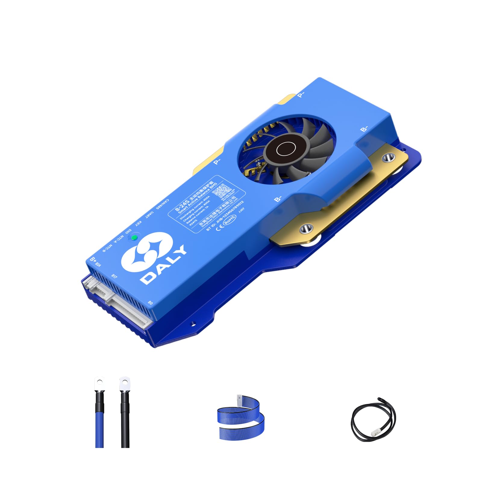
Image 1.1: DALY Smart Active Balance BMS R24TS-400A. This image displays the BMS unit with its fan, highlighting key features such as 8-24S battery strings, 400A charge/discharge current, 1A balance current, built-in Bluetooth, and UART+RS485+CAN communication.
2. Product Features
- Active Balancing: Features a 1A active balance current to ensure cell voltage consistency and extend battery life.
- Wide Cell Compatibility: Supports 8S to 24S battery configurations for Li-ion, LiFePO4, and LTO battery types.
- High Current Capacity: Capable of handling up to 400A charge and discharge currents.
- Integrated Bluetooth: Allows for wireless monitoring and parameter adjustment via a mobile application.
- Multiple Communication Interfaces: Includes UART, RS485, and CAN for versatile integration with various systems.
- Comprehensive Protection: Provides protection against overcharge, over-discharge, overcurrent, short circuit, and over-temperature.
- Preload Protection: Prevents damage from inrush current during initial connection.
- Fault Connection Protection: Designed to mitigate risks from incorrect wiring.
- Parallel Protection: Supports safe operation in parallel battery pack configurations.
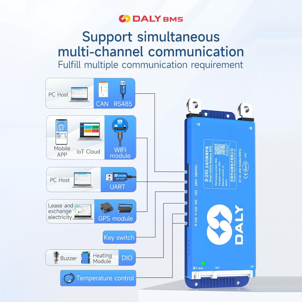
Image 2.1: Multi-channel communication support. This diagram illustrates how the DALY BMS can connect to various modules like PC Host (CAN, RS485, UART), Mobile APP, IoT Cloud, WiFi module, GPS module, Key switch, Buzzer, Heating Module, and Temperature control.
3. Package Contents
Verify that all items listed below are included in your package:
- Smart Active Balance BMS Unit
- P-&-B- cable
- Screws (2 Pcs)
- Sampling cable (Balance wires)
- B+ cable
- NTC (Temperature sensor - one standard, two optional)
- User Manual
- Packaging box
- RS485/CAN port cable

Image 3.1: Contents of the DALY BMS package. This image visually represents the Smart Active Balance BMS unit, P-&-B- cable, screws, sampling cable, B+ cable, NTC sensor, user manual, packaging box, and RS485/CAN port cable.
4. Installation and Wiring
Proper installation is crucial for the safe and effective operation of the BMS. Always ensure the battery pack is disconnected from any power sources before beginning installation. Refer to the wiring diagrams provided in the user manual for your specific battery configuration.
4.1 General Wiring Steps:
- Connect B- to Battery Negative: Connect the thick black B- wire from the BMS to the main negative terminal of your battery pack.
- Connect P- to Load/Charger Negative: Connect the thick black P- wire from the BMS to the negative terminal of your load and charger.
- Connect B+ to Battery Positive: Connect the thick red B+ wire from the BMS to the main positive terminal of your battery pack.
- Connect Balance Wires: Carefully connect the balance wires (sampling cable) to each cell of your battery pack, starting from B0 (negative of the first cell) up to B24 (positive of the last cell). Ensure the correct order and polarity.
- Connect Temperature Sensors (NTC): If applicable, connect the NTC sensors to the battery cells to monitor temperature.
- Connect Communication Cables: Connect the Bluetooth module, RS485, CAN, or UART cables as required for your application.
4.2 Protection Features During Wiring:

Image 4.1: Preload Protection. This image illustrates the wiring for preload protection, which manages inrush current during initial connection to prevent component damage.

Image 4.2: Fault Connection Protection. This diagram shows how the BMS is designed to protect against incorrect wiring, highlighting critical connection points.

Image 4.3: All-Round Protection. This image provides a general overview of the comprehensive protection wiring, ensuring safety across various operational parameters.

Image 4.4: Parallel Protection. This diagram illustrates the wiring configuration for parallel battery packs, ensuring balanced operation and protection across multiple units.
5. Operating Instructions
5.1 Initial Power-Up:
After completing all wiring, double-check connections for correctness and security. Power on the battery pack. The BMS should initialize, and its status indicator (if present) will illuminate.
5.2 Bluetooth Monitoring:
Download the official DALY BMS mobile application from your device's app store. Enable Bluetooth on your mobile device and open the app. The app should detect the BMS. Connect to the BMS to view real-time battery data, including cell voltages, total voltage, current, temperature, and protection status. You can also adjust certain parameters through the app.
5.3 Communication Interfaces (RS485/CAN/UART):
For integration with external systems (e.g., PC host, industrial controllers), connect the appropriate communication cable (RS485, CAN, or UART) to the BMS. Refer to the DALY communication protocol documentation for detailed information on data exchange and control commands.
6. Maintenance
- Regular Inspection: Periodically inspect all wiring connections for tightness and signs of corrosion or damage.
- Firmware Updates: Check the DALY official website or app for any available firmware updates. Follow the provided instructions carefully for any update procedures.
- Cleanliness: Keep the BMS unit clean and free from dust and debris to ensure proper heat dissipation.
- Environmental Conditions: Ensure the BMS operates within its specified temperature and humidity ranges.
7. Troubleshooting
- BMS Not Powering On: Verify all main power connections (B-, P-, B+) and ensure the battery pack has sufficient voltage. Check the fuse if applicable.
- Cell Imbalance: If the app shows significant cell voltage differences, ensure the balance wires are correctly connected and not damaged. The active balancing function will work to equalize cells over time.
- Overcurrent/Short Circuit Protection Triggered: Disconnect the load immediately. Identify and resolve the cause of the overcurrent or short circuit before reconnecting.
- Communication Issues: Ensure Bluetooth is enabled and the app is updated. For wired communication (RS485/CAN/UART), check cable connections and verify communication settings.
- Sensing Circuitry Issues: In rare cases, strong electrical impulses (e.g., from lightning strikes or severe electrical transients) can damage sensing circuitry. Ensure the battery pack and BMS are adequately shielded and grounded in environments prone to such events. If sensing issues persist, contact DALY support.
8. Specifications
| Feature | Specification |
|---|---|
| Model Number | R24TS-400A |
| Battery Type Compatibility | Li-ion, LiFePO4, LTO |
| Cell Count | 8S-24S |
| Nominal Voltage Range | 24V-84V (depending on cell count and type) |
| Max. Charge/Discharge Current | 400A |
| Active Balance Current | 1A |
| Communication Interfaces | Built-in Bluetooth, RS485, CAN, UART |
| Dimensions (L x W x H) | 19.6 x 10.9 x 2.6 cm (approx.) |
| Weight | 660 Grams (approx.) |
| Manufacturer | Dongguan Daly Electronics Co., Ltd |

Image 8.1: BMS Current and Size Specifications. This table provides dimensional data and current ratings for various DALY BMS models, including 100A, 150A/200A, and 250A/300A/400A/500A versions. Note that the R24TS-400A falls under the 250-500A category.
9. Application Scenarios
The DALY Smart Active Balance BMS is suitable for a wide range of applications requiring robust battery management:
- Electric two-wheelers (e.g., scooters, motorcycles)
- Home energy storage systems
- Electric tricycles
- Outdoor energy storage solutions
- Electric bicycles
- Electric wheelchairs
- Lead-Acid to Lithium battery upgrades
- Automated Guided Vehicles (AGV)
- Lease battery swapping stations
- RV energy storage

Image 9.1: Application Scenarios. This image displays various uses for the DALY BMS, including electric two-wheelers, home energy storage, electric tricycles, outdoor energy storage, electric bicycles, electric wheelchairs, Lead-Acid to Lithium upgrades, AGVs, lease battery swapping, and RV energy storage.
10. Safety Information
- Always wear appropriate personal protective equipment (PPE) when handling batteries and BMS units.
- Ensure all connections are secure and insulated to prevent short circuits.
- Do not attempt to disassemble or modify the BMS unit. Unauthorized modifications can lead to damage, fire, or injury.
- Keep the BMS away from water, moisture, and flammable materials.
- In case of smoke, unusual odors, or excessive heat, immediately disconnect the battery pack and seek professional assistance.
- Installation should be performed by qualified personnel with knowledge of battery systems and electrical safety.
11. Warranty and Support
For warranty information, technical support, or service inquiries, please refer to the contact details provided with your purchase or visit the official DALY website. Keep your purchase receipt as proof of purchase for warranty claims.
