1. Introduction
This manual provides essential instructions for the installation, operation, and maintenance of your DALY Smart Active Balance Battery Management System (BMS) model R24TM-150A. This BMS is designed to protect and manage Li-ion, LiFePO4, and LTO battery packs with 4 to 8 series cells (4S-8S) and a continuous current rating of 150A. It features built-in Bluetooth for smart monitoring and communication capabilities including RS485 and CAN.
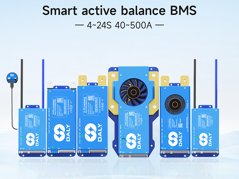
2. Product Overview
The DALY Smart Active Balance BMS R24TM-150A is a sophisticated battery protection board that ensures the safety and longevity of your battery pack. It actively balances cell voltages, prevents overcharge, over-discharge, overcurrent, and short circuits, and includes temperature protection. The integrated Bluetooth module allows for real-time monitoring and parameter adjustment via a mobile application.


3. Specifications
| Feature | Specification |
|---|---|
| Model Number | R24TM-150A |
| Supported Battery Types | Li-ion, LiFePO4, LTO |
| Series Cells (Strings) | 4S-8S |
| Continuous Discharge Current | 150A |
| Continuous Charge Current | 150A |
| Active Balance Current | 1A |
| Communication Interfaces | Built-in Bluetooth, RS485, CAN, UART |
| Input Voltage | 12V-24V |
| Output Voltage | 12V (DC) |
| Product Dimensions (L x W x H) | 6.97 x 2.6 x 0.63 inches (177 x 66 x 16 mm) |
| Item Weight | 9.7 ounces (275 Grams) |

4. Package Contents
Verify that all items listed below are included in your package:

- Smart Active Balance BMS Unit
- P-&B- Cable
- Screws (2 Pcs)
- Sampling Cable (Balance Leads)
- B+ Cable
- NTC Temperature Sensor (One standard, two optional)
- User Manual
- Packaging Box
- RS485/CAN Port Cable
5. Setup and Installation
Proper installation is crucial for the safe and effective operation of the BMS. Always ensure power is disconnected from the battery pack before beginning installation.
5.1 Wiring Diagram
Refer to the following diagrams for correct wiring connections. Incorrect wiring can damage the BMS and battery pack.

5.2 Connection Procedure
It is critical to connect all components in the correct sequence to prevent damage to the BMS or battery. Follow these steps carefully:
- Prepare Battery Pack: Ensure all individual battery cells are at a similar state of charge before connecting the BMS.
- Connect Balance Leads: Connect the sampling cable (balance leads) to each individual cell of your battery pack, starting from B0 (negative terminal of the first cell) and proceeding sequentially to B+ (positive terminal of the last cell). Ensure the order is correct according to your battery configuration (4S-8S).
- Connect B- Terminal: Connect the main negative terminal of the battery pack to the B- terminal on the BMS.
- Connect P- Terminal: Connect the load/charger negative terminal to the P- terminal on the BMS.
- Connect B+ Terminal: Connect the main positive terminal of the battery pack to the B+ terminal on the BMS.
- Connect Communication Cables: If using, connect the RS485/CAN port cable and NTC temperature sensor.
- Verify Connections: Double-check all connections for correctness and secure fit before applying power.
Warning: Incorrect connection order can lead to immediate damage to the BMS and potentially the battery pack. Always follow the specified sequence.
6. Operating Instructions
6.1 Bluetooth App Connection
The DALY Smart BMS features integrated Bluetooth for convenient monitoring and configuration via a mobile application.
- Download App: Search for "BalanceBMS" on your iOS or Android device's app store and install it.
- Enable Bluetooth: Ensure Bluetooth is enabled on your mobile device.
- Connect to BMS: Open the "BalanceBMS" app and follow the on-screen instructions to connect to your DALY Smart BMS. The app will typically detect nearby BMS devices.
6.2 Monitoring and Configuration
Once connected, the app provides access to various parameters and settings:
- Real-time Data: Monitor individual cell voltages, total battery voltage, charge/discharge current, temperature, and State of Charge (SOC).
- Active Balance Status: View the status of the active balancing process, which helps equalize cell voltages for optimal performance and extended battery life.
- Protection Status: Check for any active protection warnings or faults (e.g., overcharge, over-discharge, overcurrent, high temperature).
- Parameter Adjustment: Adjust various protection parameters and operational settings as needed (advanced users only).
- Data Logging: The BMS may offer data logging capabilities for historical performance analysis.
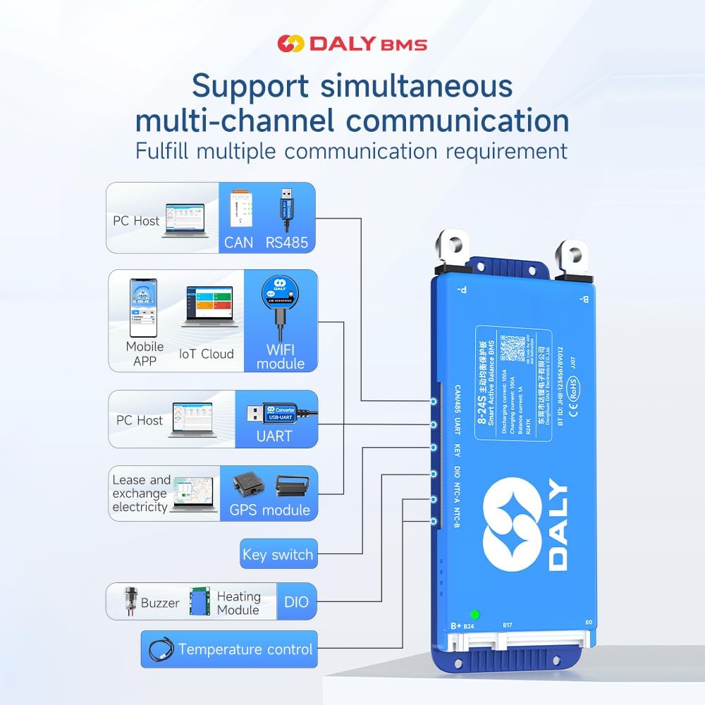
6.3 Communication Interfaces (RS485/CAN/UART)
For advanced integration and monitoring, the BMS supports RS485, CAN, and UART communication protocols. These interfaces allow connection to external devices such as PC hosts, IoT cloud modules (with optional WiFi module), GPS modules, and other control systems.
7. Maintenance
The DALY Smart Active Balance BMS is designed for minimal maintenance. However, regular checks can help ensure optimal performance and longevity of your battery system:
- Visual Inspection: Periodically inspect the BMS and all wiring for any signs of damage, corrosion, or loose connections.
- App Monitoring: Regularly check the BMS status via the "BalanceBMS" app to monitor cell voltages, temperatures, and overall battery health. Address any warnings or alerts promptly.
- Firmware Updates: Check for available firmware updates for the BMS through the app or manufacturer's website to ensure you have the latest features and bug fixes.
- Cleanliness: Keep the BMS free from dust and debris. Ensure adequate ventilation if installed in an enclosure.
8. Troubleshooting
If you encounter issues with your DALY Smart Active Balance BMS, consider the following troubleshooting steps:
8.1 Compatibility Check
Ensure your BMS is compatible with your battery type and configuration. For example, a BMS designed for LiFePO4 batteries may not function correctly with Li-ion batteries, even if the cell count is similar.

8.2 Common Issues and Solutions
- BMS Not Powering On/No Data:
- Verify all wiring connections, especially the main power and balance leads, are secure and in the correct sequence.
- Check the battery pack voltage to ensure it is within the operational range of the BMS.
- Cells Not Balancing:
- Confirm that the balance leads are correctly connected to each cell.
- Check the active balance current setting in the app.
- Ensure the battery pack is not severely out of balance, which may require external balancing before BMS can effectively manage.
- Over-Discharge/Over-Charge Protection Triggered:
- Check the battery voltage. If over-discharged, charge the battery. If over-charged, stop charging.
- Review the protection parameters in the app to ensure they are set appropriately for your battery type.
- BMS Not Communicating via Bluetooth:
- Ensure Bluetooth is enabled on your mobile device and the BMS is powered on.
- Try restarting the app and your mobile device.
- Ensure no other devices are interfering with the Bluetooth signal.
- Unexpected Behavior/Malfunction:
- Review the installation steps carefully, especially the connection order. Incorrect installation is a common cause of issues.
- If the issue persists, contact customer support for further assistance.
9. Warranty and Support
The DALY Smart Active Balance BMS R24TM-150A comes with an 18-month warranty from the date of purchase, covering manufacturing defects. For warranty claims or technical assistance, please contact DALY customer service. When contacting support, please provide your product model number (R24TM-150A) and a detailed description of the issue.
While DALY strives to provide friendly customer service, it is recommended to thoroughly review this manual and ensure correct installation as per instructions, as improper setup is a frequent cause of operational issues.


