1. Introduction
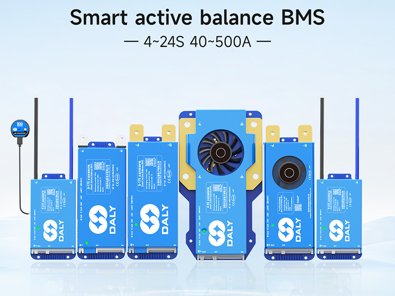
This manual provides detailed instructions for the installation, operation, and maintenance of your DALY Smart Active Balance BMS (Battery Management System). This intelligent BMS is designed for Li-ion, LifePO4, and LTO battery packs, supporting 8 to 24 series configurations with a continuous discharge current of 500A. It features built-in Bluetooth, RS485, and CAN communication for comprehensive monitoring and control.
2. Product Features
- Smart Active Balancing: Continuous 1A active balance current with peak current up to 1.2A, ensuring cell voltage equalization for extended battery life.
- Wide Compatibility: Supports 8-24S Li-ion, LifePO4, and LTO battery packs.
- Multi-channel Communication: Integrated Bluetooth, RS485, and CAN for versatile monitoring and control via PC software or mobile application.
- Comprehensive Protection: Protects batteries from overcharge, overdischarge, overcurrent, short circuits, and high-temperature shutdown.
- Parallel Battery Pack Support: Designed for safe and efficient parallel connection of battery packs.
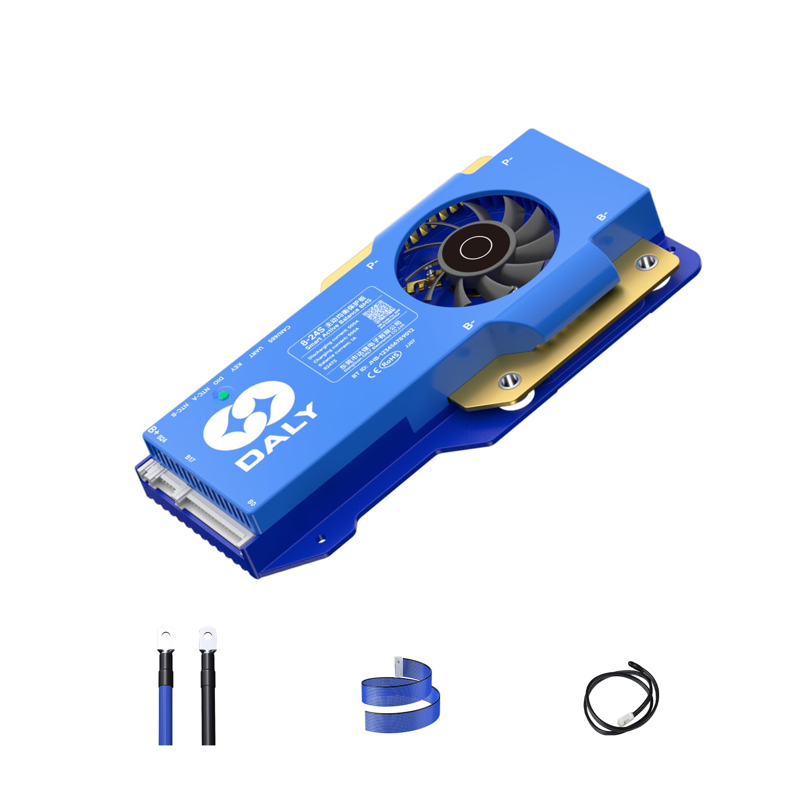
3. Package Contents
Verify that all items listed below are included in your package:
- Smart Active Balance BMS
- P-&B- cable
- Screws (2 Pcs)
- Sampling cable
- B+ cable
- NTC (One standard, two optional)
- User Manual
- Packaging box
- RS485/Can port cable

4. Setup and Installation
Proper installation is crucial for the safe and efficient operation of the BMS. Follow these steps carefully.
4.1. Battery Pack Wiring
When assembling your battery pack, ensure you correctly identify the total positive and total negative terminals. Pay close attention to the B- and P- terminals on the BMS.
- Connect the black B- wire to the total negative terminal of the battery pack.
- Connect the red B+ wire to the total positive terminal of the battery pack.
- Connect the sampling wires in sequence, starting from the negative terminal (B0) and progressing to the positive terminals of each cell string (B1, B2, etc.).
- Important: When soldering the wires, ensure they are soldered in the correct order before plugging them into the BMS. Misfiring protection is limited to 6 strings; incorrect wiring for more than 6 strings can damage your BMS.
- If using a BMS compatible with more strings than your battery pack (e.g., an 8-17S BMS for an 8S pack), seal the remaining unused sampling cables with insulation tape.
4.2. Wiring Verification
Before connecting the sampling cable to the BMS, verify the voltage of each wire using a multimeter.
- Place the black probe of the multimeter on the B0 wire (total negative).
- Place the red probe on B1, then B2, and so on. The voltage readings should increase incrementally.
- If the multimeter displays positive voltage readings that increase step by step, the wiring is correct.
- Caution: During testing, do not let the two probes touch each other, as this may cause a cable short circuit.
4.3. Final Connections
- Insert the NTC (temperature sensor) cable into the NTC port on the BMS.
- Connect the B- wire to the BMS B- terminal.
- Plug in the sampling cable connector to the corresponding port on the BMS.
- Connect the B+ wire to the BMS B+ terminal.
- If the BMS's green light is on, the BMS is working properly.
5. Operating Instructions
The DALY Smart Active Balance BMS offers multiple ways to monitor and configure its parameters.
5.1. Mobile Application (APP)
Download the "BalanceBMS" app from your iOS or Android app store. The app allows you to monitor cell voltages, temperatures, and other parameters in real-time. It also supports cloud monitoring and data logging capabilities.
5.2. PC Host Software
For advanced monitoring and configuration, connect the BMS to a PC using the provided UART cable or RS485/CAN port cable. You will need to download the corresponding drivers and PC host software from the DALY website.
- Download the PC Host software and necessary drivers (CAN or RS485) from the official DALY website.
- Connect the UART cable to the BMS and your PC.
- Open the PC Host software. Select the correct communication mode (UART, RS485, or CAN) and port settings.
- The software allows you to view real-time battery data, including total voltage, current, temperature, SOC, cell voltages, and MOS temperature.
- You can also modify various parameters such as balance current, sleep time, rated capacity, and protection parameters.
- The software supports switching between Chinese and English languages.
5.3. LCD Screen (Optional Accessory)
An optional LCD screen can be connected to the UART or RS485 port to display real-time battery information and allow parameter changes via a 4.3-inch touch screen.
5.4. Key Switch (Optional Accessory)
The optional key switch can be used to switch the discharge MOSFET on and off. Other functions may also be customized.
5.5. Heating Module (Optional Accessory)
A heating module can be used in cold environments to start the BMS, ensuring optimal performance in low temperatures.
6. Maintenance
To ensure the longevity and optimal performance of your DALY Smart Active Balance BMS, consider the following maintenance tips:
- Regularly check all wiring connections for tightness and corrosion.
- Keep the BMS clean and free from dust and debris.
- Avoid exposing the BMS to extreme temperatures or moisture beyond its operating specifications.
- Monitor battery cell balance and overall battery health using the mobile app or PC software.
- Ensure proper ventilation around the BMS, especially for high-current applications.
7. Troubleshooting
If you encounter issues with your DALY Smart Active Balance BMS, refer to the following common troubleshooting steps:
| Problem | Possible Cause | Solution |
|---|---|---|
| BMS not powering on (no green light) | Incorrect B- or B+ wiring; faulty battery connection. | Verify B- and B+ connections to the battery pack. Ensure the battery pack has sufficient voltage. |
| Incorrect voltage readings in app/software | Incorrect sampling wire connection order; loose sampling wires. | Re-check sampling wire connections and order. Ensure all wires are securely attached and soldered. |
| BMS not communicating with app/PC | Bluetooth/UART/RS485/CAN connection issue; incorrect drivers/software settings. | Ensure Bluetooth is enabled on your device. Check cable connections. Verify correct COM port and baud rate in PC software. Reinstall drivers if necessary. |
| Battery cells out of balance | Balancing function disabled; significant cell voltage difference. | Ensure active balancing is enabled in the app/PC software. Allow sufficient time for balancing to occur. Check individual cell health. |
| BMS triggering protection frequently | Overcharge/overdischarge/overcurrent conditions; incorrect protection parameters. | Review battery usage and charging/discharging limits. Adjust protection parameters in the app/PC software if they are too conservative for your battery type and usage. |
8. Specifications
| Feature | Detail |
|---|---|
| Model Number | R24TS-500A |
| Battery Strings | 8-24S (24V-84V) |
| Continuous Discharge Current | 500A |
| Continuous Charge Current | 500A |
| Active Balance Current | 1A (Continuous), up to 1.2A (Peak) |
| Battery Type Compatibility | Li-ion, LifePO4, LTO |
| Communication Interfaces | Built-in Bluetooth, RS485, CAN, UART |
| Product Dimensions | 7.72 x 4.29 x 1.02 inches (196 x 109 x 26 mm) |
| Item Weight | 1.46 pounds (660 Grams) |
| Manufacturer | Dongguan Daly Electronics Co., Ltd |

9. Warranty and Support
Your DALY Smart Active Balance BMS comes with an 18-month warranty. For any questions, technical assistance, or warranty claims, please contact our customer service. You can find the "BalanceBMS" app on iOS and Android for monitoring and support.
Additional protection plans are available for purchase:
- 2-Year Protection Plan
- 3-Year Protection Plan
- Complete Protect: One plan covers all eligible past and future purchases.
10. Application Scenarios
The DALY Smart Active Balance BMS is suitable for a wide range of multi-purpose, intelligent multi-string applications, including but not limited to:
- Electric two-wheelers
- Home energy storage systems
- Electric tricycles
- Outdoor energy storage solutions
- Electric bicycles
- Lead-Acid battery upgrades to Lithium
- Electric wheelchairs
- Automated Guided Vehicles (AGV)
- Lease battery swapping stations
- RV energy storage
