1. Introduction
This manual provides comprehensive instructions for the safe and efficient operation of your Boartechs Dual Channels Digital Handheld Oscilloscope (Model: SCO_2_10M). Please read this manual thoroughly before using the device to ensure proper functionality and to prevent damage.
2. Safety Information
Always observe the following safety precautions to prevent injury or damage to the device:
- Do not operate the device in wet or damp conditions.
- Ensure the device is powered off before connecting or disconnecting probes.
- Do not exceed the maximum input voltage ratings (up to 400V continuous voltage).
- Use only the specified power adapter and accessories.
- Do not attempt to open or repair the device yourself. Refer all servicing to qualified personnel.
- Keep the device away from strong electromagnetic fields.
3. Product Overview and Features
The Boartechs Dual Channels Digital Handheld Oscilloscope is a compact and versatile tool designed for electronic repair and analysis. Key features include:
- Dual channels for simultaneous waveform display.
- Built-in DDS signal generator for testing circuits.
- Cursor measurement function for precise analysis of period, frequency, and voltage.
- One-button automatic waveform display for quick setup.
- Built-in high voltage protection module (up to 400V continuous).
- Adjustable screen brightness and background grid brightness.
- 1GB built-in storage for screen captures and waveform data.
- USB interface for connection to a computer for secondary analysis.
- FFT display function for signal spectrum analysis.
3.1 Device Layout
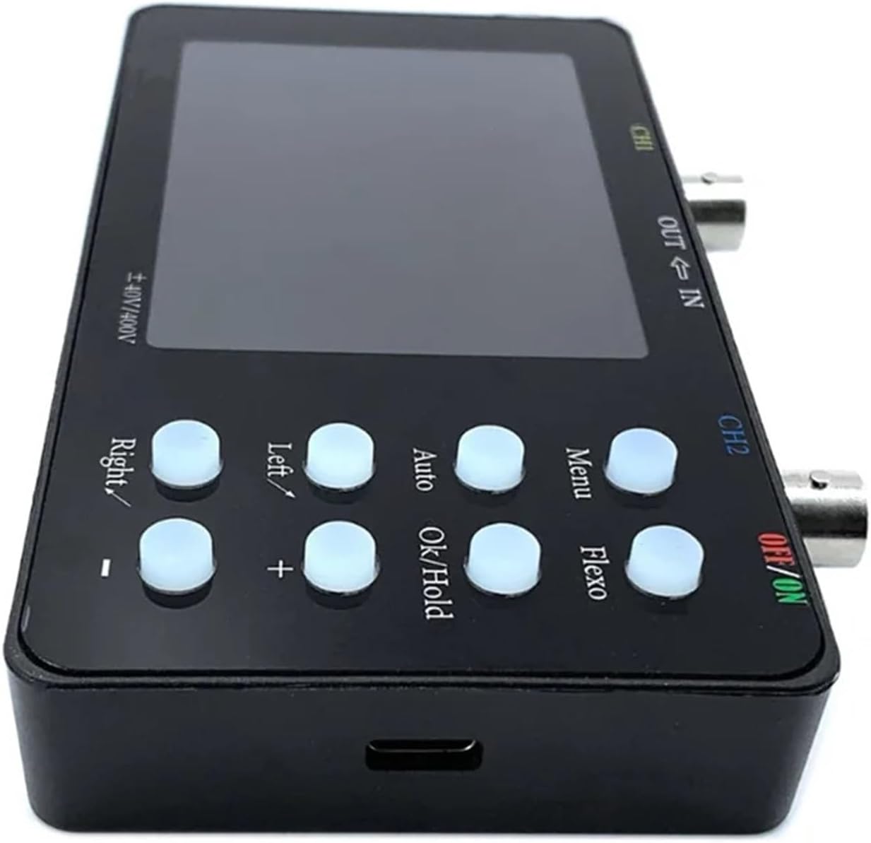
Figure 1: Side view of the oscilloscope, highlighting the CH1 and CH2 input ports, OUT/IN ports, and power button.
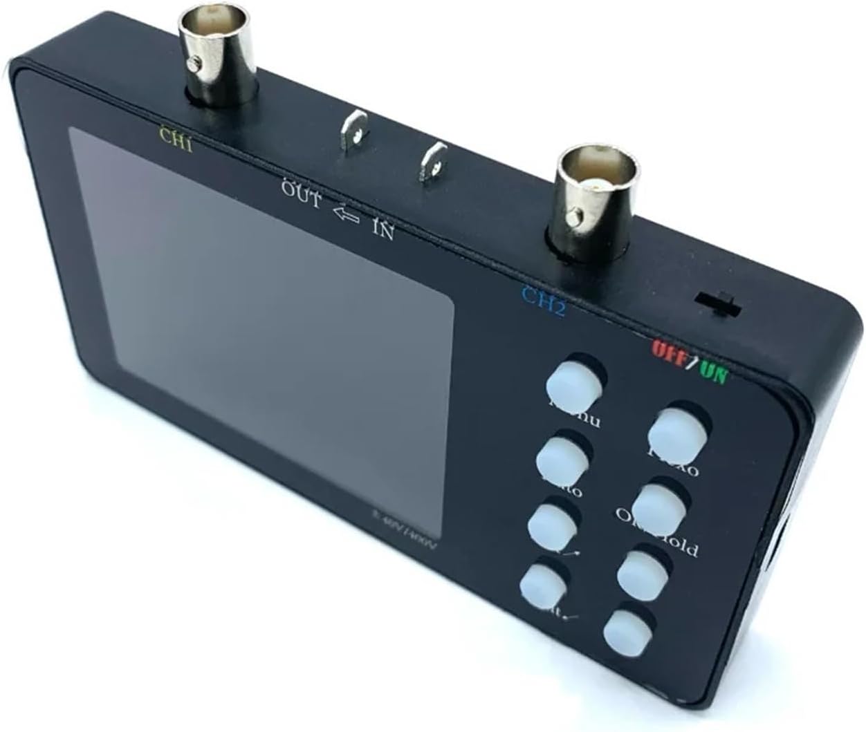
Figure 2: Side view of the oscilloscope, detailing the control buttons for navigation, auto-set, menu, and hold functions.
4. Setup
4.1 Package Contents
Verify that all items are present in the package:
- Boartechs Digital Handheld Oscilloscope
- USB Cable
- Oscilloscope Probes (quantity may vary by package)
- User Manual (this document)
4.2 Powering On/Off
- To power on, press and hold the OFF/ON button located on the side of the device until the screen illuminates.
- To power off, press and hold the OFF/ON button until the screen turns off.
4.3 Connecting Probes
- Ensure the oscilloscope is powered off before connecting probes.
- Connect the BNC connector of the oscilloscope probe to the CH1 or CH2 input port on the top of the device.
- Connect the ground clip of the probe to the ground point of the circuit under test.
- Connect the probe tip to the signal point of the circuit under test.
5. Operating Instructions
5.1 Basic Waveform Display
After powering on and connecting probes, the oscilloscope will display the input signal. Use the navigation buttons (Left, Right, +, -) to adjust horizontal (time base) and vertical (voltage scale) settings. The Auto button can automatically adjust these settings for a stable waveform display.

Figure 3: Examples of waveform displays, including dual channel measurements, Lissajous patterns, and current waveforms, demonstrating the device's analytical capabilities.
5.2 One-Button Automatic Measurement
Press the Auto button to automatically adjust the oscilloscope's settings (time base, voltage scale, trigger level) to display a stable waveform. This feature simplifies initial setup and quick signal viewing.
5.3 Cursor Measurement Function
The cursor measurement function allows for precise manual measurement of waveform parameters. Access this function via the Menu button. Use the navigation buttons to position the cursors and read out values for period, frequency, voltage, and other parameters displayed on the screen.
5.4 Built-in DDS Signal Generator
The oscilloscope includes a Direct Digital Synthesis (DDS) signal generator. To use it, connect the OUT port to the circuit you wish to test. Access the signal generator settings through the Menu to select waveform type (e.g., sine, square, triangle), frequency, and amplitude.
5.5 Saving Waveforms and Screenshots
The device has 1GB of built-in storage. To save the current waveform or screen display, press the OK/Hold button. Follow the on-screen prompts to save the data. Saved data can be reviewed later or transferred to a computer.
5.6 Connecting to a Computer (USB)
Connect the oscilloscope to a computer using the provided USB cable. This allows for data transfer, secondary analysis of saved waveforms, and potentially firmware updates. Refer to the specific software instructions for your operating system.
5.7 FFT Display Function
The Fast Fourier Transform (FFT) display function allows you to analyze the frequency components of a signal. Access this mode via the Menu. This is useful for identifying harmonics, noise, and other frequency-domain characteristics of your signal.
5.8 Adjusting Screen Brightness
You can adjust the screen brightness and background grid brightness through the device's menu settings to suit your viewing environment.
6. Maintenance
6.1 Cleaning
To clean the device, power it off and disconnect all probes and cables. Use a soft, dry cloth to wipe the exterior. For stubborn dirt, a slightly damp cloth with mild detergent can be used, ensuring no liquid enters the device. Do not use abrasive cleaners or solvents.
6.2 Storage
When not in use, store the oscilloscope in a cool, dry place, away from direct sunlight and extreme temperatures. Protect it from dust and physical impact. It is recommended to store it in its original packaging or a protective case.
7. Troubleshooting
| Problem | Possible Cause | Solution |
|---|---|---|
| Device does not power on. | Low battery or power cable not connected. | Charge the battery or connect the USB power cable. Ensure the power button is pressed correctly. |
| No waveform displayed. | Probe not connected, signal too small/large, or incorrect settings. | Check probe connections. Use the Auto button. Adjust vertical (Volts/Div) and horizontal (Time/Div) scales. Verify trigger settings. |
| Unstable waveform. | Incorrect trigger settings. | Adjust the trigger level and trigger mode (e.g., Edge, Auto). Use the Auto button. |
| Screen is too dim/bright. | Screen brightness settings. | Adjust screen brightness through the device's menu. |
8. Specifications
| Parameter | Value |
|---|---|
| Model Number | SCO_2_10M |
| Digital Channels | 2 |
| Bandwidth | 10 MHz |
| Real Time Sampling Rate | 50 MSa/s |
| Record Length | 20 kbit |
| Display Size | 3.0 - 4.9 Inches |
| Display Resolution | 320*240 Pixels |
| Max Continuous Voltage | 400V |
| Item Weight | 7.1 ounces (approx. 201g) |
| Package Dimensions | 1.18 x 0.79 x 0.39 inches (approx. 3 x 2 x 1 cm) |
9. Warranty and Support
Boartechs products are designed for reliability and performance. This product comes with a standard manufacturer's warranty against defects in materials and workmanship. For specific warranty terms, please refer to the warranty card included with your product or contact Boartechs customer support.
For technical support, troubleshooting assistance, or service inquiries, please visit the official Boartechs website or contact their customer service department. Please have your product model number (SCO_2_10M) and purchase information ready when contacting support.