1. Introduction
This manual provides essential instructions for the safe and effective operation of your Boartechs TO1204D Digital Oscilloscope. The TO1204D is a versatile 4-channel touch screen digital oscilloscope featuring a built-in 25MHz signal source and multimeter functions. It is designed for various electrical testing, measurement, and inspection applications.
Please read this manual thoroughly before using the device and retain it for future reference.
2. Safety Information
To prevent electric shock or personal injury, and to avoid damage to the oscilloscope or the equipment under test, observe the following safety precautions:
- Use the oscilloscope only as specified in this manual.
- Do not open the oscilloscope casing. Refer servicing to qualified personnel.
- Do not operate the oscilloscope in wet or damp conditions.
- Do not operate the oscilloscope in explosive atmospheres.
- Ensure proper ventilation to prevent overheating.
- Use only the power adapter and accessories supplied or recommended by the manufacturer.
- Always connect the ground lead of the test probe to the circuit ground before connecting the input lead.
- The device features a built-in high voltage protection module, capable of withstanding up to 400V continuous voltage. However, always exercise caution and avoid exceeding specified input limits.
3. Package Contents
Verify that all items are present and in good condition. If any items are missing or damaged, contact your supplier.
- Boartechs TO1204D Digital Oscilloscope
- Oscilloscope Probes (Quantity may vary)
- Power Adapter
- USB Cable
- User Manual (this document)
4. Product Overview
The Boartechs TO1204D is a compact and portable digital oscilloscope with a 7-inch touch screen display. It integrates oscilloscope, signal generator, and multimeter functionalities into a single device.
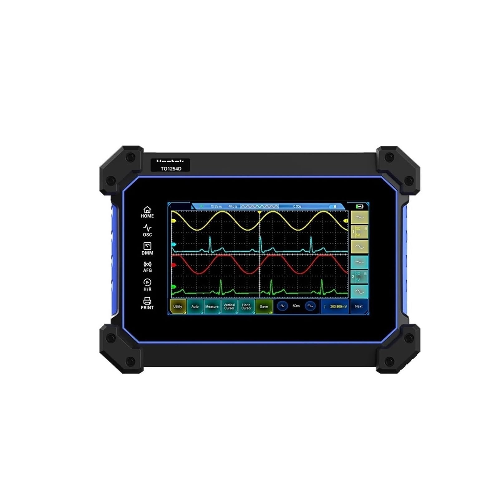
Figure 4.1: Front view of the Boartechs TO1204D Digital Oscilloscope, showing the screen and side controls.

Figure 4.2: Detailed front view of the oscilloscope, highlighting the 7-inch display with waveform visualization.
4.1 Touch Screen Interface
The device features an 800x480 pixel touch screen for intuitive control and waveform analysis. You can adjust screen brightness and background grid brightness to suit your viewing preferences.

Figure 4.3: A hand demonstrating touch screen interaction for waveform manipulation and settings adjustment.
4.2 Input/Output Ports
The rear panel of the oscilloscope provides various input and output ports for connectivity.

Figure 4.4: Rear view of the oscilloscope, displaying the AFG (Arbitrary Function Generator) output and four channel inputs (CH1, CH2, CH3, CH4).
Key ports include:
- AFG Output: For the built-in DDS signal generator.
- CH1-CH4: Four oscilloscope input channels.
- USB Interface: For connection to a computer for data transfer and secondary analysis.
- Power Input: For connecting the power adapter.
5. Setup
Follow these steps to set up your Boartechs TO1204D Digital Oscilloscope:
- Power Connection: Connect the provided power adapter to the oscilloscope's power input port and then to a suitable power outlet.
- Probe Connection: Connect the oscilloscope probes to the desired input channels (CH1-CH4) on the rear panel. Ensure a secure connection.
- Grounding: Always connect the ground clip of the probe to the ground point of the circuit under test before connecting the probe tip to the signal point.
- Power On: Press the power button to turn on the oscilloscope. The device will boot up and display the main interface.
6. Operating Instructions
The TO1204D offers various functions accessible via its touch screen and dedicated buttons.
6.1 Basic Oscilloscope Operation
- One-Button Automatic Adjustment: The oscilloscope is equipped with an efficient one-button automatic function. Press the dedicated 'Auto' button or select the 'Auto' option on the screen to automatically adjust vertical, horizontal, and trigger settings to display the measured waveform clearly. This eliminates tedious manual adjustments.
- Vertical Scale (Volts/Div): Adjust the vertical scale to control the amplitude of the displayed waveform. Use the touch screen controls or dedicated knobs (if present) to change the Volts/Div setting for each channel.
- Horizontal Scale (Time/Div): Adjust the horizontal scale to control the time base of the displayed waveform. This changes the time represented by each horizontal division on the grid.
- Trigger Settings: Configure the trigger level, mode (e.g., Edge, Pulse), and source to stabilize repetitive waveforms.
6.2 Measurement Functions
- Cursor Measurement: Utilize the cursor measurement function for convenient manual measurement of waveform parameters such as period, frequency, and voltage. Activate cursors from the measurement menu and drag them on the screen to the desired points.
- Automatic Measurements: The oscilloscope can perform various automatic measurements (e.g., Vpp, Vmax, Vmin, Freq, Period, Rise Time, Fall Time). Select these from the measurement menu.
6.3 Signal Generator (DDS)
The built-in DDS signal generator can output various waveforms. Access the signal generator function from the main menu. Configure waveform type (e.g., Sine, Square, Triangle), frequency, and amplitude using the touch screen controls. Connect the AFG output port to your circuit.
6.4 Multimeter Function
Switch to the multimeter mode to perform basic electrical measurements such as voltage, current, and resistance. Connect test leads to the appropriate multimeter input jacks (V/Ω/C, COM, mA, A) located on the side panel.
6.5 Data Storage and Connectivity
- Waveform Saving: The device includes 1GB of built-in storage space. Use the 'Save' function to store waveforms and screen captures.
- USB Interface: Connect the oscilloscope to a computer using the provided USB cable. This allows for secondary analysis of captured waveforms and data transfer using compatible software.
6.6 FFT Display Function
The FFT (Fast Fourier Transform) display function allows you to analyze the frequency spectrum characteristics of a signal. Activate FFT mode from the display or analysis menu to view the signal in the frequency domain.
7. Maintenance
Proper maintenance ensures the longevity and accuracy of your oscilloscope.
- Cleaning: Clean the oscilloscope's exterior with a soft, damp cloth. Do not use abrasive cleaners or solvents. For the screen, use a screen-specific cleaning solution and a microfiber cloth.
- Storage: When not in use, store the oscilloscope in a dry, dust-free environment, away from direct sunlight and extreme temperatures.
- Probe Care: Handle probes carefully. Avoid bending or stressing the probe cables. Store probes properly to prevent damage.
- Calibration: Periodic calibration by qualified service personnel is recommended to maintain measurement accuracy.
8. Troubleshooting
If you encounter issues with your oscilloscope, refer to the following common problems and solutions:
- No Power:
- Ensure the power adapter is securely connected to both the oscilloscope and a working power outlet.
- Check if the power outlet is functional.
- No Waveform Display:
- Verify that the probe is correctly connected to the input channel and the circuit under test.
- Check the probe's attenuation setting (1X, 10X) and ensure it matches the oscilloscope's setting.
- Use the 'Auto' button to automatically adjust settings.
- Adjust the vertical (Volts/Div) and horizontal (Time/Div) scales.
- Check trigger settings; ensure the trigger level is within the signal's amplitude.
- Unstable Waveform:
- Adjust the trigger level and trigger mode.
- Ensure the signal is stable and within the oscilloscope's bandwidth.
- Touch Screen Unresponsive:
- Restart the device.
- Ensure the screen is clean and free of debris.
If the problem persists, contact customer support.
9. Specifications
| Feature | Specification |
|---|---|
| Model Number | TO1204D (also TO1154D/TO1254D variants) |
| Digital Channels | 4 |
| Bandwidth | 150MHz / 200MHz / 250MHz (Model dependent) |
| Real Time Sampling Rate | 1GSa/S |
| Max Waveform Capture Rate | 30,000wfm/s |
| Record Length | 8M |
| Display Size | 7 Inches & Above |
| Display Resolution | 800*480 Pixels |
| Built-in Storage | 1GB |
| Signal Source | 25MHz DDS Signal Generator |
| High Voltage Protection | Up to 400V continuous voltage |
| Item Weight | 14.1 ounces |
| Package Dimensions | 1.18 x 0.79 x 0.39 inches |
| Assembly Required | No |
| Number of Pieces | 1 |
10. Warranty and Support
Boartechs products are designed for reliability and performance. For warranty information, technical support, or service inquiries, please refer to the warranty card included with your product or contact your point of purchase. Keep your purchase receipt as proof of purchase.


