
sloHEXtted industrial wireless remote control
sloHEXtted Wireless Crane Remote Control System User Manual
Model: industrial wireless remote control
1. Introduction
This manual provides essential information for the safe and effective use of the sloHEXtted Wireless Crane Remote Control System. This system is designed for industrial applications, including overhead bridge, travelling, and gantry cranes, offering precise control over a range of up to 100 meters. It features a 12-channel button configuration, two transmitters, and a receiver compatible with 110-460V AC/DC power supplies. The system is built with an IP65 dust-proof and waterproof rating, ensuring reliable operation in demanding environments.

Figure 1: The sloHEXtted wireless crane remote control in use, demonstrating its 100-meter operational range for various crane types.
2. Safety Information
Always prioritize safety when operating industrial machinery. Read and understand all instructions before use. Failure to follow safety guidelines may result in serious injury or equipment damage.
- Emergency Stop: The remote control is equipped with a prominent red E-Stop button. In case of an emergency, press this button immediately to halt all crane operations. Ensure the E-Stop is functional before each use.
- Authorized Personnel: Only trained and authorized personnel should operate this equipment.
- Environmental Conditions: While the system is IP65 rated for dust and water resistance, avoid exposing it to extreme conditions beyond its specifications.
- Inspection: Regularly inspect the transmitters and receiver for any signs of damage, wear, or loose connections. Do not operate damaged equipment.
- Interference: Be aware of potential radio interference sources in the operating environment that could affect control signals.

Figure 2: Detail of the EU Standard Emergency Stop button, designed for immediate cessation of operations and housed within a reinforced nylon shell for durability.
3. Product Overview
The sloHEXtted Wireless Crane Remote Control System consists of two handheld transmitters and one receiver unit. The transmitters feature an ergonomic design for comfortable handling and durable silicone-wrapped buttons for tactile feedback and longevity.
3.1 Components
- Transmitters (x2): Handheld units with 12 control buttons, an E-Stop button, and status LEDs.
- Receiver (x1): The main unit that connects to the crane's control system, featuring a wiring diagram and status indicators.
- Accessories: Includes Y-type fork terminals for wiring and mounting hardware.
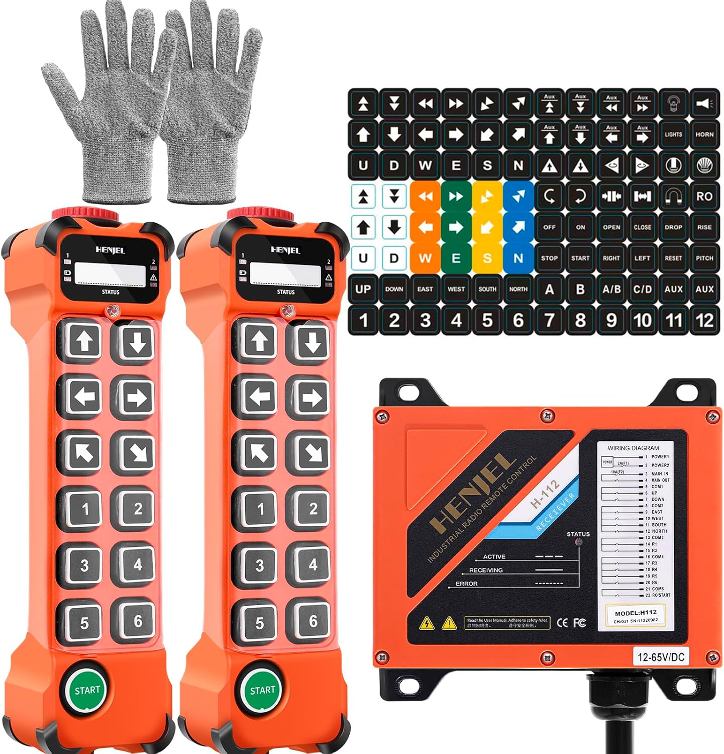
Figure 3: Overview of the sloHEXtted wireless crane remote control system, including transmitters, receiver, and accessories.
3.2 Transmitter Features

Figure 4: Detailed view of the transmitter, illustrating its ergonomic design and key functional indicators.
- Emergency Stop Push Button: Red, twist-release button for immediate system shutdown.
- LED Indicators: LED 1, LED 2, Low Battery, Error, and Status LED provide operational feedback.
- Silicone Buttons: Durable and comfortable for extended use.
- ON/HORN Button: Activates the system and can be configured for horn function.
- Start Button: Initiates operation after E-Stop release.
4. Specifications
| Feature | Detail |
|---|---|
| Model Number | industrial wireless remote control |
| Item Weight | 5.02 pounds |
| Product Dimensions | 11 x 8.2 x 3.9 inches |
| Size (Variant) | 2 Transmitters+Receiver |
| Color (Variant) | 110-460V AC/DC |
| Power Source | AC/DC |
| Voltage | 110-460 Volts (Receiver) |
| Number of Pieces | 1 (System) |
| Included Components | 2 Transmitters, 1 Receiver |
| Special Features | Brass mounting hole reserved on receiver back |
| Material (Buttons) | Silicone (Momentary system, reprogrammable with USB cable) |
| Protection Rating | IP65 (Dust-proof and waterproof) |
| Control Range | 100 meters (328 feet) |

Figure 5: Physical dimensions of the transmitter and receiver, including the receiver's wiring diagram for installation reference.
5. Setup and Installation
Proper installation of the receiver unit is crucial for safe and reliable operation. Consult a qualified electrician for wiring if you are unsure.
5.1 Receiver Mounting
- Select a secure location near the crane's control panel, ensuring it is protected from excessive vibration and heat.
- Utilize the reserved brass mounting holes on the back of the receiver for secure attachment.
- Ensure adequate clearance for wiring and access to the internal components.
5.2 Wiring the Receiver
Refer to the wiring diagram provided on the receiver unit (also shown in Figure 5) and the crane's electrical schematics. Use the provided Y-type fork terminals for secure and efficient connections.
- Power Connection: Connect the receiver to a stable power source within the specified voltage range (110-460V AC/DC).
- Control Outputs: Connect the receiver's output terminals to the corresponding control inputs of the crane's contactors or relays. Each channel corresponds to a specific crane function (e.g., UP, DOWN, EAST, WEST).
- Grounding: Ensure the receiver is properly grounded to prevent electrical hazards.
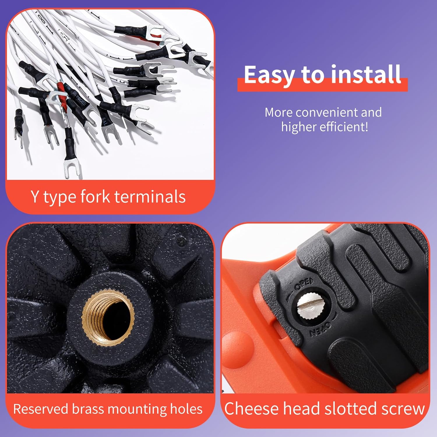
Figure 6: Components facilitating easy installation, including Y-type fork terminals and secure mounting points.
5.3 Pairing and Reprogramming
The transmitters and receiver are typically pre-paired. If reprogramming or pairing new transmitters is required, a USB programming cable (not included, sold separately) is necessary. The software and hardware are compatible across the series for flexible function changes.
6. Operation
Familiarize yourself with the transmitter's button layout and functions before operating the crane.
6.1 Basic Operation Sequence
- Release E-Stop: Twist the red Emergency Stop button clockwise to release it.
- Power On: Press the green START button to activate the transmitter and establish communication with the receiver. The status LED on the transmitter should indicate a successful connection.
- Control Functions: Use the directional and numbered buttons to control the crane's movements. The buttons are momentary, meaning the function is active only while the button is pressed.
- Emergency Stop: In any unsafe situation, press the red Emergency Stop button to immediately cease all operations.
6.2 Button Functions
The 12-channel system allows for various crane movements and auxiliary functions. The provided button label sheet can be used to customize and identify specific functions.

Figure 7: Example button labels for customizing transmitter functions.
- Directional Buttons: Typically control UP/DOWN, EAST/WEST, NORTH/SOUTH movements.
- Numbered Buttons (1-6): Can be assigned to various auxiliary functions or additional movements.
- Auxiliary Buttons: May include functions like Lights, Horn, Open, Close, Drop, Rise, Pitch, or other custom controls depending on programming.
7. Maintenance
Regular maintenance ensures the longevity and reliable performance of your wireless crane remote control system.
- Cleaning: Clean the transmitter and receiver surfaces periodically with a soft, damp cloth. Avoid using harsh chemicals or abrasive cleaners.
- Battery Replacement: The transmitters require batteries (not included). Replace batteries promptly when the low battery indicator illuminates to prevent operational interruptions.
- Inspection: Routinely check all cables and connections for wear, fraying, or corrosion. Ensure the receiver's housing is sealed and free from damage.
- Storage: When not in use for extended periods, store the transmitters in a dry, clean environment away from extreme temperatures.
8. Troubleshooting
This section addresses common issues you might encounter. For problems not listed here, contact customer support.
| Problem | Possible Cause | Solution |
|---|---|---|
| System not responding | E-Stop engaged, low transmitter battery, receiver not powered, out of range, interference. | Release E-Stop, replace batteries, check receiver power, move closer to receiver, check for interference sources. |
| Intermittent control | Weak signal, interference, damaged antenna. | Ensure clear line of sight, identify and mitigate interference, inspect receiver antenna. |
| Transmitter LEDs not lighting up | Dead batteries, internal fault. | Replace batteries. If issue persists, contact support. |
| Receiver Status LED indicates error | Internal fault, wiring issue. | Refer to the receiver's wiring diagram and LED error codes (if available). Contact support if unresolved. |

Figure 8: LED signals on the transmitter and receiver provide visual cues for diagnosing operational status and potential issues.
9. Warranty and Support
For warranty information, technical support, or to purchase replacement parts and accessories (such as the USB programming cable), please contact sloHEXtted customer service through their official channels or the retailer where the product was purchased. Keep your purchase receipt for warranty claims.
Related documentsindustrial wireless remote control


Ask a question about this manual
Ask about setup, troubleshooting, compatibility, parts, safety, or missing instructions. Manuals+ will review the question and use this page’s manual context to help answer it.