
1. Introduction
This manual provides essential information for the safe and efficient operation of your Anern 3200W Hybrid Solar Inverter, model AN-SCI-ECO. This off-grid inverter combines the functions of an inverter and a battery charger, providing a pure sine wave output from 24V DC to 220V/230V AC. It features an 80A MPPT solar charger with a wide PV input range of 30-400VDC and is compatible with various 24V battery types, including lead-acid and lithium batteries. This inverter does not support 3-phase or 2-phase systems. Please read this manual thoroughly before installation and use.
2. Safety Instructions
Always follow these safety precautions to prevent injury and damage to the inverter:
- Ensure all wiring is correctly connected according to the instructions and local electrical codes.
- Install appropriate circuit breakers for each circuit.
- Do not connect the AC output directly to a power outlet.
- The starting power for inductive loads must be at least three times the rated power of the appliance.
- Protect against short circuits, overcurrent, undervoltage, overload, and over-temperature.
- Install the inverter in a well-ventilated area, away from bedrooms, as cooling fans generate noise during operation.
- Ensure the battery is connected before starting the inverter.

Figure 2.1: Inverter's Multiple Protection Features. This image illustrates the various safety mechanisms integrated into the inverter, such as protection against overcurrent, low voltage, short circuits, overheating, and overloading, ensuring safe operation.
3. Product Overview
The Anern AN-SCI-ECO is a versatile hybrid solar inverter designed for off-grid applications. It integrates an inverter, an 80A MPPT solar charger, and a 60A AC battery charger into a single unit.

Figure 3.1: Anern AN-SCI-ECO Hybrid Solar Inverter. This image highlights the inverter's all-in-one functionality, combining a hybrid inverter, an 80A MPPT solar charger, a 60A AC charger, and a 3000W inverter.
Key Features:
- Pure Sine Wave Output: Provides stable and clean power suitable for sensitive electronics.
- High-Efficiency MPPT Solar Charger: 80A MPPT controller with a wide PV input voltage range of 30-400VDC, maximizing solar energy harvesting.
- Multi-Mode Charging: Offers four charging modes (Solar Priority, Solar Only, Utility Priority, Solar Hybrid and Utility) and three output modes (Solar Priority, Utility Priority, SBU) to meet diverse application requirements.
- Battery Compatibility: Supports 24V lead-acid, gel, LiFePO4, and other lithium batteries (minimum 100AH capacity required).
- Comprehensive Protection: Includes short circuit, overcurrent, undervoltage, overload, and over-temperature protection.
4. Specifications
| Feature | Specification |
|---|---|
| Brand | Anern |
| Model Name | AN-SCI-ECO |
| Rated Power | 3.2 KW (3200 W) |
| Peak Output Power | 3000 W |
| Input Voltage (DC) | 24 V |
| Output Voltage (AC) | 230 V |
| Waveform | Pure Sine Wave |
| MPPT Voltage Range | 30-400 VDC |
| Max PV Voltage | 400 VDC |
| Max MPPT Charging Current | 80 A |
| Max AC Charging Current | 60 A |
| Efficiency | 95.83% |
| Display Type | LCD |
| Product Dimensions (L x W x H) | 35.5 cm x 20 cm x 49 cm |
| Minimum Battery Capacity | 100 AH |
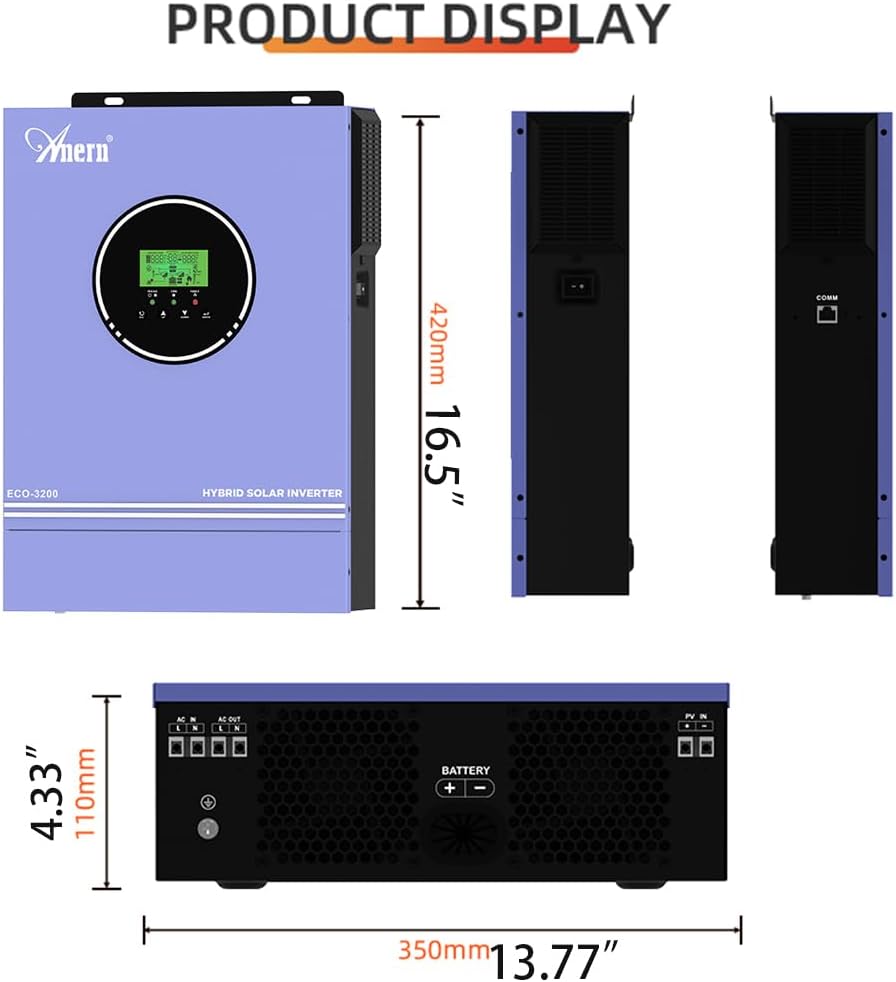
Figure 4.1: Product Views. This image provides various perspectives of the inverter, showcasing its design and form factor.

Figure 4.2: Charging Currents and Battery Compatibility. This image details the maximum charging currents for both MPPT and AC, along with the types of 24V batteries compatible with the inverter.
5. Setup and Installation
5.1 Cable Sizing Recommendations:
- Battery Cable: 1x 6AWG (14 mm²), Torque: 2 Nm (max)
- AC Cable: 12AWG, Torque: 1.2 Nm
- PV Cable: 1x 16AWG, Torque: 1.2 Nm (max)
5.2 Connection Procedure:
- Ensure all electrical connections are made correctly and securely.
- Install appropriate switches for each circuit (battery, PV, AC input, load).
- Connect the 24V battery to the inverter. The battery capacity must not be less than 100AH. For lithium batteries, set item 05 to "USER" and adjust parameters 26/27/29 as per the battery manufacturer's instructions.
- Connect the solar panels (PV input) to the inverter.
- Connect the AC utility input (if used).
- Connect your electrical loads to the AC output of the inverter.
5.3 Startup Sequence:
- First, turn on the battery switch.
- Then, turn on the inverter.
- Next, turn on the photovoltaic (PV) switches.
- Finally, turn on the utility (grid) and load switches.
5.4 Shutdown Sequence:
To shut down the system, follow the startup sequence in reverse order.

Figure 5.1: Typical Wiring Diagram. This diagram illustrates the standard connections for a solar inverter system, including solar panels, battery, utility, and loads.
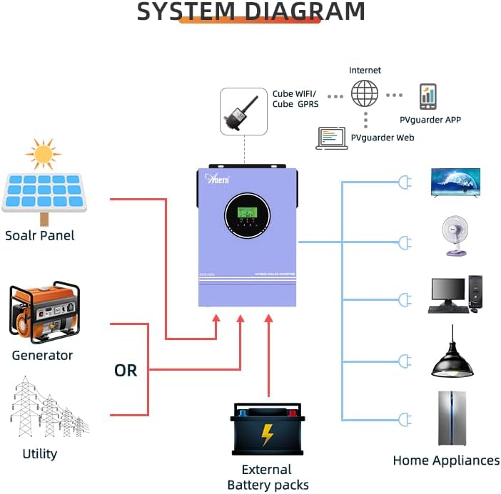
Figure 5.2: System Diagram. This diagram provides an overview of how the hybrid solar inverter integrates with solar panels, optional generator/utility, battery storage, and household appliances.
6. Operating Modes
The inverter offers flexible charging and output modes configurable via the LCD screen to suit various energy requirements.
6.1 Charging Modes:
- Solar Priority: Solar power is prioritized for charging the battery.
- Solar Only: Only solar power is used for charging.
- Utility Priority: Utility power is prioritized for charging.
- Solar Hybrid and Utility: A combination of solar and utility power is used for charging.
6.2 Output Modes:
- Solar Priority (SUB): Prioritizes solar power, then utility.
- Utility Priority (USB): Prioritizes utility power, then solar.
- SBU (Solar-Battery-Utility): Prioritizes solar, then battery, and finally utility. When using this mode, connect the battery first, then set item 05 to "USER" to prioritize PV, then battery, then grid. The indicator will glow purple.

Figure 6.1: Charging and Output Modes. This diagram visually explains the different charging and output configurations available for the inverter.
Note on PV Power Display: The inverter's PV input display shows the power consumed by the load and battery, not the total power generated by the solar panel. For example, if the PV input is 400V but the display shows only a few or a few hundred watts, this is normal as the load only draws the necessary power.
7. Maintenance
- Regularly inspect all connections for tightness and corrosion.
- Keep the inverter's ventilation openings clear to ensure proper airflow and prevent overheating.
- Clean the exterior of the inverter with a dry cloth. Do not use liquids or abrasive cleaners.
- The inverter's cooling fans will generate noise during operation. This is normal. Ensure the inverter is installed in a location where fan noise is not disruptive, such as a basement or storage room.
8. Troubleshooting
Refer to the following table for common error codes and their solutions:
| Error Code / Warning | Description | Solution |
|---|---|---|
| bP (Warning) | Battery not connected. | Connect the battery. The warning will disappear. |
| Error Code 05 | Output short circuit or internal component temperature exceeds 120°C. | 1. Check wiring for proper connection and remove any incorrect loads. 2. Check if airflow is blocked or if ambient temperature is too high. |
| Error Code 02 | Internal inverter component temperature exceeds 100°C. | Check if airflow is blocked or if ambient temperature is too high. |
| Error Code 03 | Battery voltage too high or battery overcharged. | 1. Check if battery specifications and quantity meet requirements. 2. If a damaged part is suspected, contact support for a replacement. |
| Error Code 51/52/55 | General internal error. | Restart the device. If the error persists, contact support for a replacement of the damaged part. |
| Error Code 59 | PV voltage exceeded limit. | Ensure PV input voltage is within the specified range (30-400VDC). |
9. Warranty and Support
For warranty information, technical support, or service inquiries, please refer to the documentation provided with your purchase or contact Anern customer service. Keep your purchase receipt as proof of purchase.
Anern is committed to customer satisfaction and provides support for its solar energy products. For further assistance, please visit the official Anern website or contact your local distributor.


