1. Introduction
The AVXANKTG TVPS1-63 series is an advanced dual-display adjustable overvoltage, undervoltage, and overcurrent protection device designed for DIN rail mounting. It provides comprehensive electrical protection for connected equipment by monitoring voltage and current levels and automatically disconnecting the load when parameters exceed set limits. This device features automatic recovery, real-time voltage and current display, and user-adjustable protection thresholds, ensuring stable and safe operation of electrical systems.
2. Safety Information
Please read and understand all safety instructions before installation and operation. Failure to follow these instructions may result in electric shock, fire, or serious injury.
- Installation and maintenance should only be performed by qualified electricians.
- Ensure the power supply is disconnected before any wiring or installation work.
- Verify that the device's voltage and current ratings match your electrical system requirements.
- Do not operate the device in wet or damp conditions.
- Do not attempt to repair or modify the device. Contact qualified personnel for service.
- Ensure proper grounding according to local electrical codes.
3. Product Overview
3.1 Features
- Overvoltage Protection
- Undervoltage Protection
- Overcurrent Protection
- Automatic Recovery after fault clearance
- Real-time Voltage Display (Voltage Measurement)
- Real-time Current Display (Current Measurement)
- Adjustable Voltage and Current Calibration
- Fault Query Function
- Restore Factory Settings Option
- DIN Rail Installation
3.2 Components
The device features a compact design with a dual digital display and control buttons on the front panel. Input and output terminals are clearly marked.

Figure 1: Front view of the AVXANKTG TVPS1-63 protector. It shows two digital displays for voltage and current, indicator lights for protection status, and four control buttons: Power, SET, Up, and Down. Input (IN) and Output (OUT) terminals are visible at the top and bottom.
3.3 Specifications
| Parameter | Description |
|---|---|
| Model | TVPS1-63 |
| Power Supply | 230VAC 50/60Hz |
| Maximum Load Current | 1~40A / 1~63A / 1~80A adjustable (depending on model variant) |
| Overvoltage Protection Range | 230V~300V~OFF (Default: 270V) |
| Overvoltage Recovery Range | 225V--295V (Default: 250V) |
| Overvoltage Action Time | 0.1s~30s (Default: 1s) |
| Overvoltage Recovery Delay | 1s~500s (Default: 30s) |
| Undervoltage Protection Range | 140V--210V--OFF (Default: 170V) |
| Undervoltage Recovery Range | 145V--215V (Default: 190V) |
| Undervoltage Action Time | 0.1s~30s (Default: 1s) |
| Undervoltage Recovery Delay | 1s~500s (Default: 30s) |
| Overcurrent Adjustment Range | 1-40A / 1-63A / 1-80A (depending on model variant) |
| Overcurrent Action Time | 0.1s~30s (Default: 1s) |
| Overcurrent Recovery Delay | 1s~500s (Default: 30s) |
| Power-on Delay Time | 1s~500s (Default: 10s) |
| Power Consumption | <2W |
| Motor Life | 100,000 times |
| Installation Method | 35mm DIN Rail |
| Dimensions (Approx.) | 35mm (W) x 85mm (H) x 65mm (D) |
| Item Weight | 1.76 ounces (approx. 50g) |
4. Installation
The TVPS1-63 protector is designed for easy installation on a standard 35mm DIN rail.
4.1 Mounting
- Ensure all power to the circuit is OFF at the main breaker.
- Locate a suitable position on a 35mm DIN rail within your electrical panel.
- Hook the top edge of the protector onto the DIN rail.
- Press the bottom of the protector firmly until it clicks into place on the rail.
4.2 Wiring
Refer to the markings on the device for correct input (IN) and output (OUT) connections. The device is typically wired in series with the load it is protecting.
- Connect the incoming live (L) and neutral (N) wires from the power source to the 'IN' terminals at the top of the device.
- Connect the outgoing live (L) and neutral (N) wires to the load from the 'OUT' terminals at the bottom of the device.
- Ensure all connections are tight and secure to prevent loose contacts and overheating.
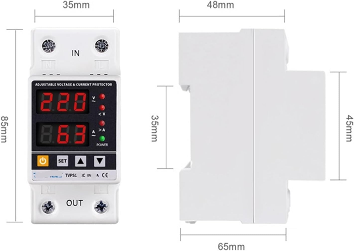
Figure 2: Dimensions of the AVXANKTG TVPS1-63 protector. The front view shows a width of 35mm and height of 85mm. The side view shows a depth of 65mm and a height of 45mm for the main body, with the DIN rail clip adding to the total height.
5. Operation
5.1 Display Indicators
- Top Display: Shows real-time voltage (V).
- Bottom Display: Shows real-time current (A).
- V (Red LED): Illuminates when overvoltage protection is active.
- <V (Red LED): Illuminates when undervoltage protection is active.
- >A (Red LED): Illuminates when overcurrent protection is active.
- POWER (Green LED): Illuminates when the device is powered on and operating normally.
5.2 Control Buttons
- Power Button (⏻): Toggles the output power ON/OFF.
- SET Button: Enters parameter setting mode. Press repeatedly to cycle through parameters.
- Up Button (▲): Increases parameter values or navigates menus.
- Down Button (▼): Decreases parameter values or navigates menus.
5.3 Parameter Settings
To adjust protection parameters:
- Press the SET button to enter the setting mode. The first parameter will flash.
- Use the Up (▲) and Down (▼) buttons to adjust the value.
- Press SET again to confirm the value and move to the next parameter.
- Repeat steps 2 and 3 for all desired parameters.
- After setting the last parameter, the device will automatically save the settings and exit the setting mode, or you can long-press SET to exit.
Adjustable parameters include:
- Overvoltage Protection Value (UVP)
- Overvoltage Recovery Voltage (UVR)
- Overvoltage Protection Action Time (UVA)
- Overvoltage Recovery Delay Time (UVD)
- Undervoltage Protection Value (LVP)
- Undervoltage Recovery Voltage (LVR)
- Undervoltage Protection Action Time (LVA)
- Undervoltage Recovery Delay Time (LVD)
- Overcurrent Adjustment Range (OCA)
- Overcurrent Action Time (OCT)
- Overcurrent Recovery Delay Time (OCD)
- Power-on Delay Time (PDT)
5.4 Calibration
- Voltage Calibration: Press and hold the Up (▲) button for more than 3 seconds to enter voltage calibration mode. Use Up (▲) and Down (▼) to adjust the voltage reading by ±10%. Press SET to save and exit.
- Current Calibration: Press and hold the Down (▼) button for more than 3 seconds to enter current calibration mode. Use Up (▲) and Down (▼) to adjust the current reading by ±5%. Press SET to save and exit.
5.5 Restore Factory Settings
To restore all parameters to their default factory settings, press and hold the Down (▼) button for more than 12 seconds. The display will indicate a reset, and the device will restart with default values.
5.6 Fault Query
To query the last fault recorded, press the Up (▲) button for more than 12 seconds. The display will show the fault code or parameter that triggered the protection. Press any button to exit fault query mode.
6. Maintenance
The AVXANKTG TVPS1-63 protector requires minimal maintenance.
- Periodically inspect the device and its wiring for any signs of damage, loose connections, or overheating.
- Keep the device clean and free from dust and debris. Use a dry, soft cloth for cleaning. Do not use liquid cleaners.
- Ensure adequate ventilation around the device to prevent heat buildup.
7. Troubleshooting
| Problem | Possible Cause | Solution |
|---|---|---|
| Device not powering on | No input power; incorrect wiring; device fault. | Check main power supply. Verify wiring connections. If problem persists, contact support. |
| Output power is off, and a red LED (V, <V, or >A) is lit. | Overvoltage, undervoltage, or overcurrent protection activated. | Check the power supply voltage/current. Reduce load if overcurrent. The device should auto-recover after the delay once conditions normalize. |
| Device trips frequently. | Protection parameters set too sensitively; unstable power supply; overloaded circuit. | Adjust protection thresholds to appropriate levels. Consult an electrician to check power stability or circuit load. |
| Display shows incorrect voltage/current. | Calibration error. | Perform voltage or current calibration as described in Section 5.4. |
| Cannot adjust parameters. | Not in setting mode; buttons unresponsive. | Press the SET button to enter setting mode. If buttons are unresponsive, try power cycling the device. |
8. Warranty and Support
For warranty information or technical support, please contact your retailer or the manufacturer, AVXANKTG, through their official channels. Keep your purchase receipt as proof of purchase.


