1. Introduction
This manual provides essential information for the safe and efficient operation of your Aoleaby Photoelectric Switch Sensor, model BJ7M-TDT-P. Please read this manual thoroughly before installation and use, and keep it for future reference. This sensor is designed for reliable object detection and distance measurement in various industrial applications.
2. Safety Information
Always observe the following safety precautions to prevent injury and damage to the device:
- Ensure power is disconnected before installation, wiring, or maintenance.
- Do not exceed the specified voltage and current ratings.
- Avoid exposing the sensor to extreme temperatures, humidity, or corrosive environments.
- Do not disassemble or modify the sensor. Refer all servicing to qualified personnel.
- Protect the sensor from strong impacts or vibrations.
3. Product Overview
The Aoleaby BJ7M-TDT-P Photoelectric Switch Sensor offers robust performance for industrial automation. Key features include:
- Easy Installation and Commissioning: Designed for quick configuration and adjustment.
- Object Detection and Distance Measurement: Provides accurate sensing capabilities.
- Self-Diagnostic Functions: Includes auto-calibration and fault alarm features for simplified maintenance.
- Reliable Operation: Engineered to work effectively in complex environments, mitigating electromagnetic and optical interference.
- Fast Response Time: Suitable for high-speed production lines requiring real-time detection.
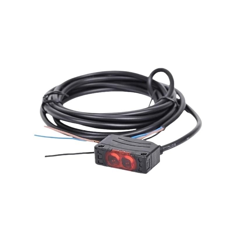
Figure 1: Aoleaby Photoelectric Switch Sensor BJ7M-TDT-P. This image shows the compact design of the sensor, typically featuring a main body with a sensing head and a cable for electrical connection.
4. Setup
4.1 Mounting
Mount the sensor securely using appropriate brackets and fasteners. Ensure the sensing surface is clear of obstructions and aligned correctly with the target object. Avoid mounting in areas with excessive vibration or direct exposure to strong light sources that could interfere with operation.
4.2 Wiring
Connect the sensor according to the wiring diagram provided with your specific unit. Typically, photoelectric sensors require power supply (DC or AC, depending on model) and an output signal wire. Ensure all connections are secure and insulated to prevent short circuits.
- Power Supply: Connect the positive (+) and negative (-) terminals to the appropriate power source.
- Output: Connect the signal output wire to your control system (e.g., PLC, relay).
- Note: Specific wire colors and functions may vary. Always refer to the label on the sensor or its packaging for precise wiring details.
5. Operating Instructions
5.1 Powering On
Once mounted and wired, apply power to the sensor. The sensor may have an indicator LED that illuminates to confirm power is supplied.
5.2 Adjusting Sensitivity/Range
Many photoelectric sensors feature a sensitivity adjustment potentiometer or button. Use a small screwdriver or follow the specific instructions for your model to adjust the detection range or sensitivity. Test the sensor's response with your target object to ensure reliable detection.
5.3 Understanding Indicators
The sensor typically includes indicator LEDs:
- Power Indicator: Usually green, indicates the sensor is powered on.
- Output Indicator: Often yellow or red, illuminates when an object is detected and the output is active.
6. Maintenance
Regular maintenance ensures optimal performance and longevity of your sensor.
6.1 Cleaning
Keep the sensing surface clean. Dust, dirt, or moisture can interfere with detection. Use a soft, dry cloth to gently wipe the lens or sensing window. Avoid abrasive cleaners or solvents.
6.2 Inspection
Periodically inspect the sensor and its wiring for any signs of damage, wear, or loose connections. Ensure mounting hardware remains secure.
6.3 Self-Diagnostic Features
The BJ7M-TDT-P sensor includes self-diagnostic and auto-calibration functions. If a fault is detected, the sensor may provide an alarm signal or change the state of an indicator LED. Consult the troubleshooting section for interpreting these signals.
7. Troubleshooting
If you encounter issues with your sensor, refer to the following common problems and solutions:
| Problem | Possible Cause | Solution |
|---|---|---|
| Sensor not powering on | No power supply; incorrect wiring; faulty power source. | Check power connections and voltage. Verify wiring against diagram. Test power source. |
| No object detection | Sensing surface dirty; object out of range; incorrect sensitivity setting; misalignment. | Clean sensing surface. Adjust sensitivity/range. Realign sensor with target. Ensure object is within detection area. |
| False detections | External light interference; reflective surfaces; excessive sensitivity. | Shield sensor from strong light. Adjust sensitivity. Reposition sensor or target. |
| Intermittent operation | Loose wiring; unstable power; electromagnetic interference. | Check all wiring connections. Ensure stable power supply. Shield cables or sensor from EMI sources. |
If the problem persists after attempting these solutions, contact customer support.
8. Specifications
| Feature | Detail |
|---|---|
| Model Number | BJ7M-TDT-P |
| Brand | Aoleaby |
| Package Dimensions | 1.18 x 0.79 x 0.39 inches |
| Item Weight | 7.1 ounces |
| Manufacturer | Aoleaby |
| Number of Pieces | 1 |
| Unit Count | 1.0 Count |
9. Warranty and Support
Aoleaby products are manufactured to high-quality standards. This product comes with a standard manufacturer's warranty against defects in materials and workmanship. For specific warranty terms and conditions, please refer to the documentation included with your purchase or visit the official Aoleaby website.
For technical support, troubleshooting assistance, or warranty claims, please contact Aoleaby customer service through the retailer where the product was purchased or via the contact information provided on the official Aoleaby website.


