
1. Introduction
This manual provides detailed instructions for the installation, operation, and maintenance of your GCSOAR 100A MPPT Solar Charge Controller. This advanced Maximum Power Point Tracking (MPPT) controller is designed for efficient charging of 12V, 24V, and 48V battery systems, supporting various battery types including Gel, Sealed, Flooded, AGM, and Lithium-Ion. It features a maximum PV input voltage of 200V and includes WiFi connectivity for remote monitoring.
The controller's high tracking efficiency (up to 99.5%) and DC/DC conversion efficiency (up to 98%) ensure optimal power harvesting from your solar panels, even under varying light conditions. Please read this manual thoroughly before installation and use to ensure proper function and safety.

Image 1.1: GCSOAR 100A MPPT Solar Charge Controller with WiFi adapter and mobile application for remote monitoring.
2. Safety Information
Always observe the following safety precautions to prevent personal injury and damage to the equipment:
- Read all instructions: Familiarize yourself with the manual before installation or operation.
- Qualified personnel: Installation and wiring should be performed by qualified personnel.
- Battery connection first: Always connect the battery to the controller before connecting solar panels. Disconnect solar panels first, then the battery.
- Correct polarity: Ensure all connections are made with correct polarity to avoid damage.
- Overcurrent protection: Install appropriate fuses or circuit breakers for both battery and solar panel circuits.
- Ventilation: Ensure adequate ventilation around the controller to prevent overheating.
- High voltage: Solar panels can produce high voltages. Exercise extreme caution during wiring.
- Battery safety: Batteries can produce explosive gases. Ensure proper ventilation and avoid sparks or flames near batteries.
3. Setup and Installation
3.1 Unboxing and Components
Upon opening the package, verify that all components are present:
- GCSOAR MPPT Solar Charge Controller
- User's Manual
- Temperature Sensor Cable
- WiFi Adapter (CM-W01)
Video 3.1: An unboxing and connection guide for the MPPT 100A Solar Charge Controller, demonstrating the contents of the package and initial wiring steps.
3.2 Wiring Connection Steps
Follow these steps for proper wiring. Always connect the battery first, then the solar panel. Disconnect in reverse order.
- Connect Battery: Connect the battery cables to the controller's battery terminals. Ensure correct polarity (positive to positive, negative to negative). The controller will power on.
- Connect Solar Panel: Connect the solar panel cables to the controller's PV terminals. Ensure correct polarity. The controller will begin charging.
- Connect Load (Optional): If using a DC load directly from the controller, connect it to the load terminals.
- Connect Temperature Sensor: Plug the temperature sensor cable into the designated port. Place the sensor near the battery for accurate temperature compensation.
- Connect WiFi Adapter: Plug the CM-W01 WiFi adapter into the RS485 port for remote monitoring.
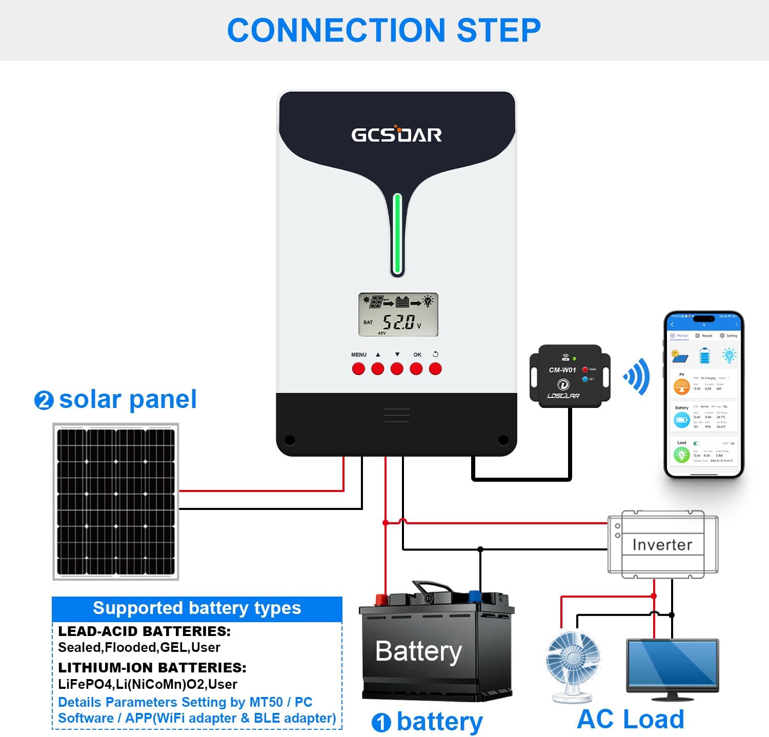
Image 3.2: Detailed connection diagram illustrating the wiring sequence for the solar charge controller, battery, solar panel, and optional AC load via an inverter.

Image 3.3: Comprehensive wiring diagram for a complete solar power system, including the GCSOAR controller, and instructions for downloading the iConnect mobile application.
3.3 Battery Type Selection
The controller is compatible with various battery types. It automatically detects 12V/24V/48V system voltage for non-Lithium batteries. For Lithium batteries, manual selection via the app is required.
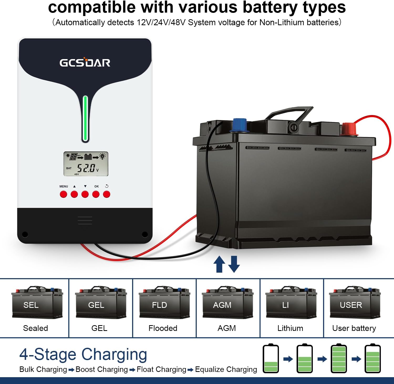
Image 3.4: The controller supports Sealed, Gel, Flooded, AGM, Lithium, and User-defined battery types, with an automatic 4-stage charging process.

Image 3.5: The GCSOAR controller and WiFi adapter are shown with various compatible battery types, emphasizing real-time monitoring capabilities.
To select the battery type:
- On the main interface, press and hold the "OK" button for 5 seconds.
- Then, briefly press the "OK" button and wait for "SEL" to flash, indicating entry into the setting status.
- Use the arrow buttons (▲/▼) to select the suitable battery type (e.g., GEL, SEL, FLD, LI, USER).
- Press and hold "OK" for 5 seconds to confirm the selection. The setting is successful when the display returns to normal operation.

Image 3.6: The controller's LCD display provides simple and intuitive programming, showing battery system, load, alarm status, charging status, real-time data, and battery type.
4. Operating Instructions
4.1 LCD Display and Button Functions
The controller features an LCD display and five buttons for navigation and settings:
- MENU: Cycles through display interfaces and enters menu settings.
- ▲ (Up): Increases values or navigates up in menus.
- ▼ (Down): Decreases values or navigates down in menus.
- OK: Confirms selections or enters setting status (long press).
- Return/Exit: Exits from any interface.
The display cycles through various parameters including battery voltage, PV voltage, charge current, battery type, and battery temperature. You can manually cycle through these by pressing the MENU button.
4.2 Remote Monitoring with WiFi App
The included CM-W01 WiFi adapter allows for remote monitoring and parameter adjustment via the "iConnect" app on Android and iOS devices. (Note: Incompatible with Samsung phones).
- Download App: Scan the QR code in the manual or visit www.ldsolarpv.com/jszc to download the "iConnect" app.
- Connect to WiFi: Follow the app's instructions to connect the controller to your local WiFi network.
- Monitor and Adjust: Once connected, you can view real-time data, historical records, and adjust various charging parameters from your smartphone.

Image 4.1: Wireless monitoring of the PV system is possible through the iConnect app on a smartphone, connected via the CM-W01 WiFi adapter.
4.3 MPPT Charging Mode
The controller utilizes MPPT technology for efficient 4-stage charging to prolong battery lifecycle:
- Bulk Charge: Maximum current charging to quickly raise battery voltage.
- Boost Charging: Constant voltage charging to ensure full charge.
- Float Charging: Maintains battery at a fully charged state with a lower voltage.
- Equalize Charging (for certain battery types): Periodically overcharges to balance cell voltages.

Image 4.2: The MPPT charging mode graph shows the four stages of battery charging, optimizing for battery health and longevity.
5. Maintenance
Regular maintenance ensures optimal performance and longevity of your solar charge controller:
- Inspect connections: Periodically check all wiring connections for tightness and corrosion.
- Clean controller: Keep the controller clean and free from dust and debris. Use a dry cloth.
- Check ventilation: Ensure the cooling fan and vents are not obstructed. The controller features efficient heat dissipation with fan cooling.
- Monitor performance: Regularly check the LCD display or the iConnect app for system parameters to ensure normal operation.
- Battery inspection: Inspect batteries for any signs of damage, swelling, or leaks.

Image 5.1: The controller is designed with a fan and aluminum heat dissipation base plate for efficient cooling and low heat generation.
6. Troubleshooting
If you encounter issues, refer to the following common problems and solutions:
- Controller not powering on: Check battery connections and ensure correct polarity. Verify battery voltage is within the controller's operating range.
- No charging from solar panels: Ensure solar panel connections are secure and have correct polarity. Check PV voltage on the display. Verify sufficient sunlight.
- WiFi connection issues: Ensure the CM-W01 adapter is properly connected. Verify your router is 2.4GHz. If using a Samsung phone, note that the app may be incompatible. Try resetting the WiFi adapter or reconfiguring through the app.
- Incorrect battery type displayed: Follow the instructions in Section 3.3 to manually select the correct battery type.
- Load not working: Check load connections and ensure the load is not exceeding the controller's rated current. Verify load mode settings.
- Undervoltage battery activation: The controller automatically activates Li-Ion batteries that have shut down due to internal BMS protection, resuming recharging.

Image 6.1: The solar charge controller automatically reactivates Lithium-Ion batteries that have entered undervoltage protection, allowing them to resume charging.
6.1 Multiple Protections
The controller incorporates multiple protection features to safeguard your system:
- PV Overcurrent Protection
- Load Overload Protection
- Battery Over Voltage Protection
- PV Short Circuit Protection
- Load Short Circuit Protection
- Battery Over Discharge Protection
- Battery Overheating Protection
- Controller Overheating Protection
- Anti-reverse Protection
- Battery Disconnect Protection
- Undervoltage Protection

Image 6.2: The controller offers comprehensive protection against various electrical faults and environmental conditions.

Image 6.3: An overview of the multiple protection features integrated into the GCSOAR controller to ensure safe operation for diverse battery chemistries.
7. Specifications
Below are the technical specifications for the GCSOAR 100A MPPT Solar Charge Controller:
| Feature | Specification |
|---|---|
| System Voltage | 12V/24V/48V Automatic |
| Charging Current Rating | 100A |
| Max PV Voltage | 200V |
| Max PV Input Power (12V System) | 1300W |
| Max PV Input Power (24V System) | 2600W |
| Max PV Input Power (48V System) | 5200W |
| MPPT Tracking Efficiency | Up to 99.5% |
| DC/DC Conversion Efficiency | Up to 98% |
| Compatible Battery Types | Gel, Sealed, Flooded, AGM, Lithium-Ion, User-defined |
| Display Type | LCD |
| Communication | WiFi (via CM-W01 adapter) |
| Cooling | Fan Cooling |
| Item Weight | 9.09 pounds |
| Package Dimensions | 14.13 x 10.28 x 5.91 inches |
| Material | Plastic |
| Color | Black |
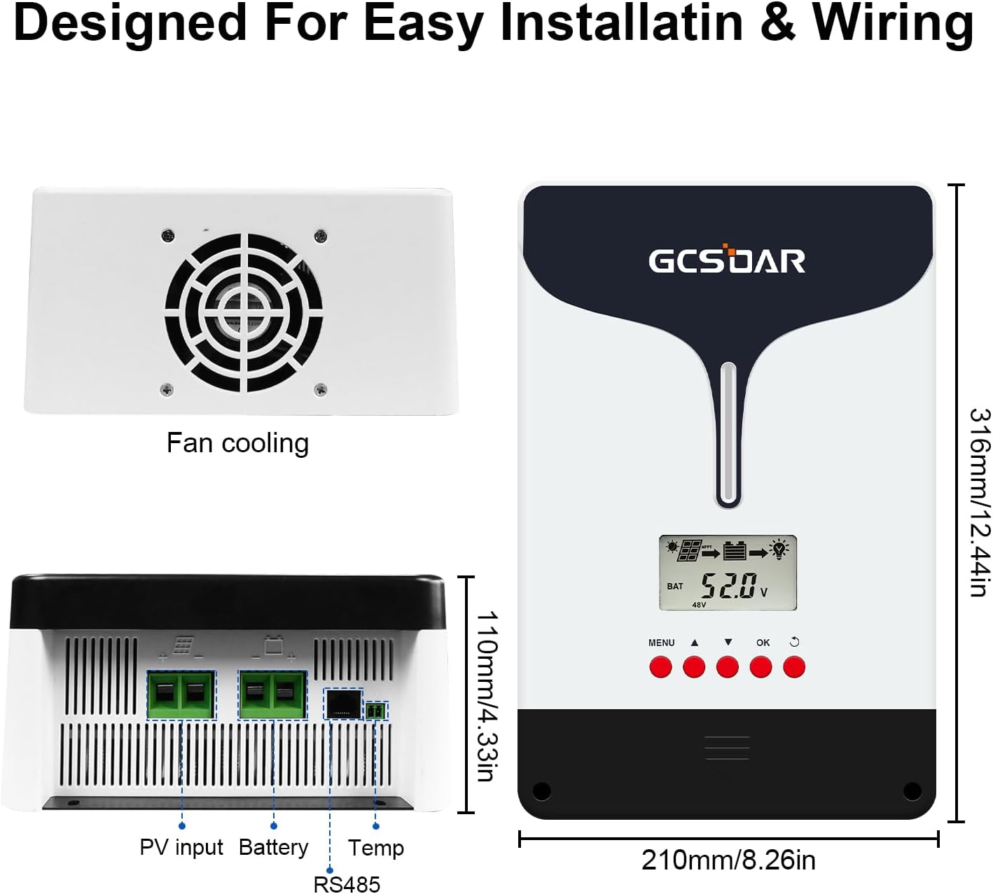
Image 7.1: Physical dimensions and port layout of the GCSOAR solar charge controller, including the fan cooling system.
8. Warranty and Support
For warranty information and technical support, please refer to the documentation included with your product or contact GCSOAR customer service. You may also visit the official GCSOAR store on Amazon for additional resources and contact details: GCSOAR Store.