Product Overview
The JFZTPVAK AC22KW Digital Voltage Power Energy Voltmeter Ammeter is a versatile instrument designed for measuring electrical parameters such as voltage, current, active power, and energy consumption. It features a large LCD screen for clear display and includes an overload alarm function for safety.

Figure 1: Front view of the Digital Voltmeter Ammeter with its accompanying Current Transformer (CT) coil.
Specifications
| Parameter | Value |
|---|---|
| Size | Approximately 85 x 47 x 28 mm (3.35 x 1.85 x 1.10 inches) |
| Maximum Current | 100A (with CT coil) / 20A (direct connection) |
| Apply to Power Grid Voltage Range | 110V-220V AC |
| Working Voltage | 85 ~ 250VAC |
| Test Voltage | 85 ~ 250VAC |
| Rated Power | 20A/5000W (for 20A model), 100A/22000W (for 100A model) |
| Working Frequency | 45-65Hz |
| Measurement Accuracy | 1.0 |
| Item Weight | 50 Grams |

Figure 2: Detailed dimensions of the Digital Voltmeter Ammeter unit.
Setup and Installation
This device requires connection to an AC power circuit. Ensure all power is disconnected before attempting installation. There are two main connection modes depending on the maximum current rating of your unit (20A or 100A).
Connection Diagrams

Figure 3: Connection diagrams for both 20A (left) and 100A (right) models. Note the direction of the arrow on the transformer for the 100A model.
20A Mode of Connection
For the 20A version, the device connects directly in series with the load. This mode is suitable for lower current applications.
- Identify the input (L and N) and output terminals on the device.
- Connect the live (L) wire from the AC power source to the input L terminal.
- Connect the neutral (N) wire from the AC power source to the input N terminal.
- Connect the output L terminal to the live input of your load.
- Connect the output N terminal to the neutral input of your load.
- Ensure all connections are secure and insulated.
100A Mode of Connection (with CT Coil)
For the 100A version, a Current Transformer (CT) coil is used to measure current indirectly. This mode is for higher current applications.
- Identify the input (L and N) terminals for power supply to the meter (AC110-250V).
- Connect the live (L) wire from the AC power source to the L terminal of the meter's power input.
- Connect the neutral (N) wire from the AC power source to the N terminal of the meter's power input.
- Pass the live wire of the circuit you wish to measure through the CT coil. Important: Ensure the direction of the arrow on the CT coil matches the direction of current flow (from source to load).
- Connect the two wires from the CT coil (red and black) to the designated CT input terminals on the meter.
- Ensure all connections are secure and insulated.
After wiring, restore power to the circuit. The device should power on and display readings.
Operating Instructions
The device operates automatically once powered on, displaying various electrical parameters on its large LCD screen. It does not require an external power supply as it draws power directly from the measured circuit.
Display Interface
The LCD screen simultaneously displays the following parameters:
- Voltage (V): Displays the current AC voltage.
- Current (A): Displays the current AC current.
- Active Power (W): Displays the real power being consumed by the load.
- Energy (kWh): Accumulates the total energy consumed over time.
- Power Factor (PF): Displays the power factor.
- Frequency (Hz): Displays the AC frequency.
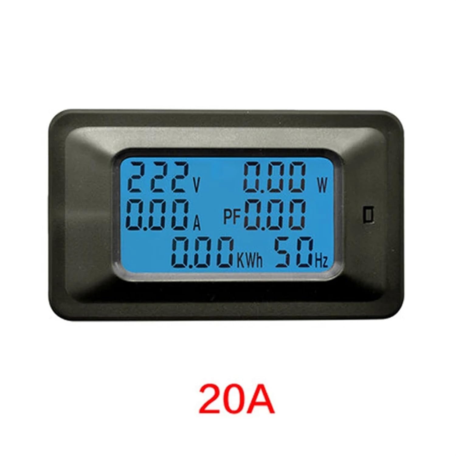
Figure 4: The 20A model of the Digital Voltmeter Ammeter, showing its display.
Key Functions
The device features a single button for interaction:
- Power Button Clear Function: This button is used to clear the accumulated energy (kWh) reading. Press and hold the button for a few seconds until the kWh reading resets to zero.
- Overload Alarm Threshold Setting: The device has a preset function for the power alarm threshold. While the exact method for setting this threshold is not detailed on the device itself, it typically involves a combination of short and long presses of the button or an internal potentiometer. Refer to the manufacturer's specific instructions if available for detailed threshold adjustment. When the power exceeds the set threshold, the backlight will flicker, and the power reading will flash to indicate an overload.
Data Storage
The device includes a power-down data storage function. This means that the accumulated energy (kWh) reading will be saved even if power is lost, ensuring continuous tracking of energy consumption.
Maintenance
To ensure the longevity and accurate operation of your digital voltmeter ammeter, follow these general maintenance guidelines:
- Cleaning: Use a soft, dry cloth to clean the device. Do not use abrasive cleaners, solvents, or immerse the device in water.
- Storage: Store the device in a cool, dry place away from direct sunlight, extreme temperatures, and high humidity.
- Handling: Avoid dropping the device or subjecting it to strong impacts, as this can damage internal components.
- Connections: Periodically check all wiring connections to ensure they remain secure and free from corrosion.
Troubleshooting
If you encounter issues with your device, consider the following common troubleshooting steps:
- No Display/No Power:
- Check if the power supply to the device is active and within the specified working voltage range (85-250VAC).
- Verify all wiring connections are correct and secure according to the setup diagrams.
- Incorrect Readings:
- For 100A models, ensure the CT coil is installed correctly and the arrow on the coil points in the direction of current flow.
- Confirm that the device model (20A or 100A) matches your application and wiring method.
- Ensure the load is connected properly and drawing power.
- Overload Alarm Constantly Active:
- Check if the actual power consumption of your load exceeds the device's rated power or the set overload alarm threshold.
- If possible, adjust the overload alarm threshold (refer to manufacturer's specific instructions).
- Display Flickering/Unstable:
- Ensure stable power supply. Fluctuations in input voltage can affect display stability.
- Check for loose connections.
If problems persist after following these steps, contact customer support.
Warranty and Support
For specific warranty information regarding your JFZTPVAK Digital Voltmeter Ammeter, please refer to the documentation provided at the time of purchase or contact the seller directly. Warranty terms typically cover manufacturing defects for a specified period.
If you require technical assistance, have questions about installation, or need to report a defect, please contact the seller or manufacturer through the platform where the product was purchased. Provide your model number (JFZTPVAK) and a detailed description of the issue to facilitate support.