1. Introduction
Thank you for choosing the ELEGRP 15A 125V Decorator Receptacle. This product is designed for reliable electrical power distribution in residential and commercial settings. It features a non-tamper resistant design, self-grounding capabilities, and a durable high-impact resistant thermoplastic construction. This manual provides detailed instructions for safe installation, operation, and maintenance to ensure optimal performance and longevity of your receptacle.

Image 1.1: Key features of the ELEGRP Decorator Receptacle, highlighting its robust construction and safety certifications.
2. Safety Information
WARNING: To avoid fire, shock, or death, turn off power at the circuit breaker or fuse box and test that power is off before wiring. All wiring should be performed by a qualified electrician or in accordance with local electrical codes.
- Always turn off power at the service panel before working with electrical outlets.
- Use only copper wire with this device. Do not use aluminum wire.
- Ensure proper grounding to prevent electrical shock.
- Do not install in wet or damp locations unless specifically rated for such environments.
- This device is non-tamper resistant. Exercise caution when children are present.

Image 2.1: The receptacle's flame-resistant properties, capable of withstanding temperatures up to 750°C.

Image 2.2: The receptacle's high-impact resistant design, built to endure accidental drops and pressure during installation.
3. Package Contents
Your ELEGRP Decorator Receptacle package includes the following items:
- 10 x ELEGRP 15A 125V Decorator Receptacles (Glossy Black)
- 10 x Matching Glossy Black Wall Plates
- Mounting Screws for each receptacle and wall plate
- Instruction Manual
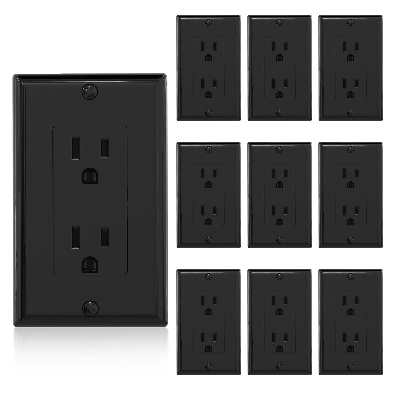
Image 3.1: A view of the ten glossy black decorator receptacles and their included wall plates.
4. Specifications
| Safety Certification | UL, CUL Listed |
| Rating (A.V.) | 15A 125V |
| Receptacle Type | Decorator Receptacle |
| Wiring Type | Quick Push-in Wiring and Side Wiring |
| Grounding | Self-Grounding |
| Product Dimensions | 4.5"L x 2.75"W x 0.97"D (114.3mm x 69.8mm x 24.6mm) |
| Material | High-Impact Resistant Thermoplastic |
| Color | Glossy Black |

Image 4.1: Detailed product specifications and dimensions of the receptacle.
5. Installation
Follow these steps for safe and correct installation of your ELEGRP Decorator Receptacle:
- Turn Off Power: Locate your circuit breaker panel and turn off the power to the outlet you will be replacing or installing. Verify power is off using a voltage tester.
- Remove Old Receptacle (if applicable): Unscrew and carefully remove the old wall plate and receptacle from the electrical box. Disconnect the wires.
- Prepare Wires: Strip approximately 1/2 inch (12.7 mm) of insulation from the ends of the electrical wires (Hot, Neutral, Ground).
- Wiring Options: The ELEGRP receptacle supports both side wiring and quick push-in wiring.
- Side Wiring (12AWG & 14AWG): Loosen the terminal screws (Brass for Hot/Black, Silver for Neutral/White, Green for Ground/Green or bare copper). Hook the appropriate wire around the screw and tighten securely.
- Push-in Wiring (14AWG ONLY): For 14AWG solid copper wire, simply push the stripped end of the wire into the corresponding hole on the back of the receptacle until it is firmly seated.
- Self-Grounding: The receptacle includes a green grounding screw and a self-grounding clip for automatic grounding when installed in a properly grounded metal electrical box. Ensure the ground wire is connected to the green screw.
- Mount Receptacle: Carefully fold the wires into the electrical box. Secure the receptacle to the electrical box using the provided mounting screws. The break-off plaster ears allow for best flush alignment with the wall.
- Install Wall Plate: Attach the glossy black wall plate over the installed receptacle using the provided screws.
- Restore Power: Turn the power back on at the circuit breaker panel. Test the receptacle to ensure it is functioning correctly.

Image 5.1: Visual guide for connecting wires using either the side screw terminals or the push-in terminals.

Image 5.2: Details of the self-grounding mechanism and break-off plaster ears for flush alignment.
Video 5.3: An official ELEGRP video demonstrating the features and installation process of a residential grade receptacle.
6. Operation
The ELEGRP Decorator Receptacle operates as a standard electrical outlet. Once properly installed and powered, simply insert the plug of your electrical device into the receptacle slots. Ensure the plug is fully inserted for a secure connection. This non-tamper resistant outlet is suitable for general-purpose use in various indoor environments.
7. Maintenance
The ELEGRP Decorator Receptacle requires minimal maintenance. Follow these guidelines to keep your outlet in good condition:
- Cleaning: The glossy finish is soil-resistant and allows for easy cleaning. Wipe the surface with a soft, damp cloth. Do not use abrasive cleaners or solvents, as these may damage the finish. Ensure power is off before cleaning.
- Inspection: Periodically inspect the receptacle and wall plate for any signs of damage, such as cracks, discoloration, or loose connections. If any damage is observed, turn off power and replace the unit.
- Loose Plugs: If plugs feel loose when inserted into the receptacle, it may indicate wear. Consider replacing the receptacle to ensure a safe and reliable connection.
8. Troubleshooting
If you encounter issues with your ELEGRP Decorator Receptacle, refer to the following troubleshooting tips:
| Problem | Possible Cause & Solution |
| No power at the outlet |
|
| Receptacle feels warm |
|
| Plug falls out easily |
|
9. Warranty and Support
ELEGRP products are manufactured to high-quality standards and are backed by a limited warranty. For specific warranty details, technical support, or assistance with your product, please refer to the warranty card included with your purchase or visit the official ELEGRP website. Do not attempt to repair the device yourself, as this may void the warranty and pose safety risks.


