
1. Introduction
Thank you for choosing the LIT-PaTH LED Combo Exit Sign with Emergency Light. This product is designed to provide reliable emergency illumination and clear exit path indication in commercial and residential settings. It features adjustable LED light heads, a durable flame-retardant housing, and a battery backup system for power outages. Please read this manual thoroughly before installation and operation to ensure proper function and safety.
2. Safety Information
WARNING: Risk of electric shock. Disconnect power before installation or servicing.
- All servicing should be performed by qualified personnel only.
- Ensure the main power supply is turned off before commencing any work on the unit.
- Do not use outdoors. This unit is designed for indoor use only.
- Mount securely in locations and at heights where it will not be readily subjected to tampering by unauthorized personnel.
- Do not mount near gas or electric heaters.
- The AC voltage requirement for this fixture is 100-300V.
- The battery in this unit is rechargeable Nickel Cadmium (NiCd). Do not dispose of batteries in fire.
- This product is UL 924 and CEC certified, ensuring compliance with safety standards.

3. Package Contents
Verify that all components are present and undamaged before proceeding with installation:
- LED Combo Exit Sign Unit with Emergency Lights
- Extra Faceplate (for double-sided configuration)
- Snap-out Chevron Directional Indicators
- Mounting Bracket / Canopy
- Wire Connectors (x2)
- Mounting Screws (x2)

4. Specifications
| Feature | Specification |
|---|---|
| Brand | LIT-PaTH |
| Model Number | LT-EL004 |
| Input Voltage | 100-300V AC (Universal) |
| Light Type | LED |
| Battery Type | NiCd (Nickel Cadmium) |
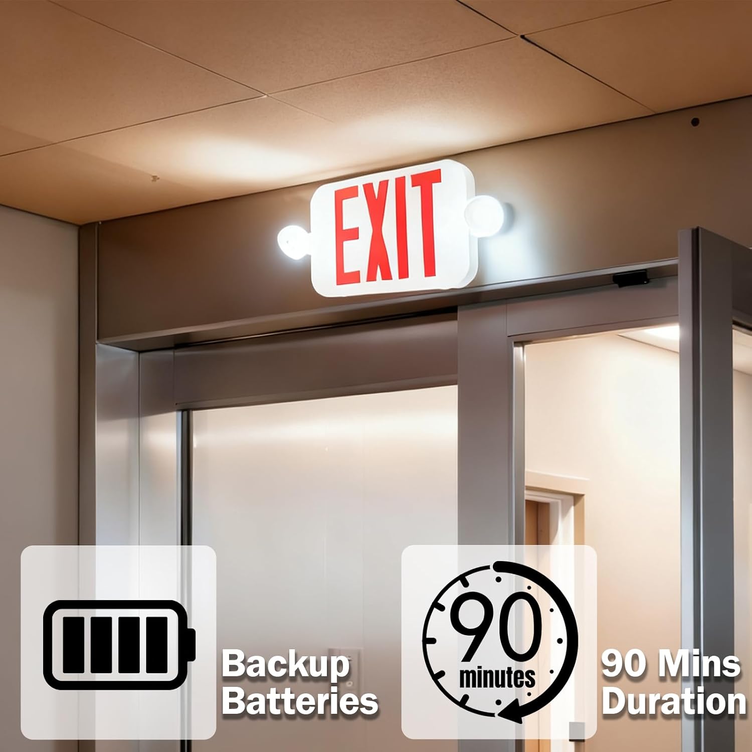
| Emergency Duration | 90+ minutes |
| Mounting Type | Ceiling Mount, Wall Mount |
| Housing Material | Injection-molded thermoplastic (UL94V-0 flame retardant) |
| Item Weight | 1.4 pounds |
| Dimensions (L x W x H) | Approx. 15.92" x 1.7" x 7.76" |

5. Installation
This unit supports both ceiling and wall mounting. Ensure power is disconnected before beginning installation.
5.1. Preparing the Unit
- Open the unit by removing the faceplate.
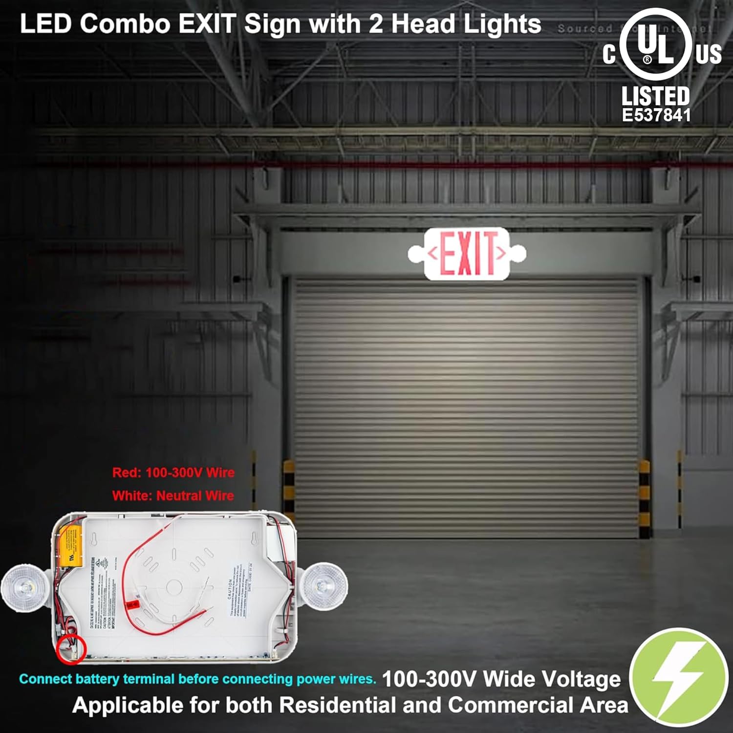
- Connect the battery: Locate the battery pack and plug its connector into the corresponding port on the circuit board. Ensure a secure connection.
- If double-sided operation is desired, remove the appropriate knockout sections from the extra faceplate and attach it to the back of the unit. Insert the snap-out chevron directional indicators as needed for the desired exit direction.

5.2. Wiring Instructions
The unit is hardwired and supports 100-300V AC. Follow local electrical codes.
- Identify the incoming AC power wires: Live (Red/Black) and Neutral (White).
- Connect the unit's red wire to the building's Live (Red/Black) wire using a wire connector.
- Connect the unit's white wire to the building's Neutral (White) wire using a wire connector.
- Ensure all connections are secure and insulated.
5.3. Mounting the Unit
Choose either ceiling or wall mount based on your application.
Ceiling Mount:
- Secure the mounting bracket/canopy to the ceiling junction box using appropriate screws.
- Feed the electrical wires through the opening in the canopy.
- Make the electrical connections as described in Section 5.2.
- Attach the exit sign unit to the mounting bracket/canopy, ensuring it is firmly secured.
Wall Mount:
- Secure the mounting bracket/canopy to the wall junction box using appropriate screws.
- Feed the electrical wires through the opening in the canopy.
- Make the electrical connections as described in Section 5.2.
- Attach the exit sign unit to the mounting bracket/canopy, ensuring it is firmly secured.

5.4. Adjusting Light Heads
The two LED light heads are rotatable 360 degrees horizontally and 180 degrees vertically, allowing you to direct emergency illumination as needed.

6. Operating Instructions
6.1. Initial Operation and Charging
- After installation and connecting to AC power, restore power to the unit.
- The 'Charging Indicator' LED (usually green) should illuminate, indicating the battery is charging. Allow the battery to charge for at least 24 hours before the first test to ensure full capacity.
6.2. Test Button Function
A 'Push-to-test' switch is located on the unit for mandated code compliance testing.
- Press and hold the 'TEST' button. The exit sign and emergency lights should illuminate, and the 'Charging Indicator' should turn off. This simulates a power outage.
- Release the 'TEST' button. The emergency lights should turn off, and the 'Charging Indicator' should re-illuminate, indicating normal AC power operation and battery charging.

7. Maintenance
Regular maintenance ensures the longevity and reliability of your emergency exit sign.
- Monthly Test: Press the 'TEST' button for 30 seconds. The emergency lights should remain illuminated for the entire duration.
- Annual Test: Disconnect AC power to the unit for 90 minutes. The emergency lights should remain illuminated for the full 90-minute period. If the lights do not stay on for 90 minutes, the battery may need replacement.
- Cleaning: Clean the exterior of the unit with a soft, damp cloth. Do not use abrasive cleaners or solvents.
- Battery Replacement: The NiCd battery has a typical lifespan of 5-7 years. If the unit fails the annual 90-minute test, replace the battery with an identical type and voltage. Ensure power is disconnected before replacing the battery.
8. Troubleshooting
If your emergency exit sign is not functioning correctly, refer to the following common issues and solutions:
| Problem | Possible Cause | Solution |
|---|---|---|
| Exit sign and emergency lights do not illuminate when AC power is on. | No AC power; Incorrect wiring; Faulty LED. | Check circuit breaker and power supply. Verify wiring connections. Contact qualified electrician if issue persists. |
| Emergency lights do not turn on during a power outage or when 'TEST' button is pressed. | Battery not connected; Battery not charged; Faulty battery. | Ensure battery is securely connected. Allow 24 hours for initial charge. Replace battery if it fails annual test. |
| 'Charging Indicator' LED is off or blinking. | No AC power; Battery fault; Circuit fault. | Check AC power. Perform battery test. If issue persists, contact customer support. |
| Emergency lights are dim. | Battery not fully charged; Aging battery. | Allow 24 hours for full charge. Replace battery if it's old or fails tests. |
9. Warranty and Support
LIT-PaTH products are designed for durability and reliability. For specific warranty details, please refer to the product packaging or contact LIT-PaTH customer service directly. If you encounter any issues not covered in this manual, or require further assistance, please reach out to the manufacturer's support team.
Contact Information: Please visit the official LIT-PaTH website or refer to your purchase documentation for customer support contact details.