1. Introduction
This manual provides detailed instructions for the assembly, operation, and maintenance of the VELLEMAN K2634 4 Triac Switch Card Assembly Kit. This kit is designed for hobbyists and electronics enthusiasts to build a circuit capable of switching AC voltages using triacs, offering an alternative to traditional relays for frequent or rapid switching applications.
2. Product Overview
The VELLEMAN K2634 is a 4-channel triac switch card. It utilizes optocouplers to ensure electrical isolation between the control circuit and the switched AC voltage, enhancing safety and reliability. Triacs are ideal for applications where frequent switching of AC loads is required, as they avoid the wear and tear associated with mechanical relay contacts.
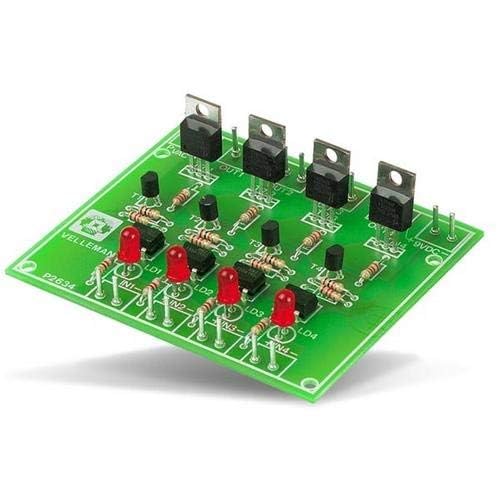
Figure 1: Assembled VELLEMAN K2634 4 Triac Switch Card. This image displays the completed circuit board with four triacs, optocouplers, resistors, and LEDs, ready for integration into an electronic project.
3. Specifications
| Feature | Specification |
|---|---|
| Triac Outputs | 4 channels |
| Output Current (uncooled) | 1.5A per channel |
| Output Current (cooled) | 4A per channel |
| Power Supply | 9VDC, 200mA |
| PCB Dimensions | 78 x 90mm (3.1 x 3.5") |
| Item Weight | 1 g |
| Country of Origin | China |
4. Assembly Instructions
This is an assembly kit. Careful soldering and component placement are required. Please follow these general guidelines:
- Preparation: Unpack all components and verify against the kit's bill of materials (not provided in this manual, refer to the kit packaging). Ensure you have a clean workspace, a soldering iron with a fine tip, solder, desoldering braid/pump, and safety glasses.
- Component Identification: Identify all resistors, capacitors, diodes, triacs, optocouplers, and other components. Pay attention to polarity for diodes, LEDs, and integrated circuits (optocouplers).
- Resistors: Solder all resistors first. These are typically non-polarized.
- Diodes and LEDs: Solder diodes and LEDs, ensuring correct polarity. The longer lead of an LED is usually the anode (+). For diodes, the band indicates the cathode (-).
- Optocouplers: Solder the optocouplers, ensuring correct orientation (usually indicated by a dot or notch on the IC and the PCB silkscreen).
- Triacs: Solder the triacs. If high current loads (above 1.5A) are anticipated, attach appropriate heatsinks to the triacs before soldering them to the PCB, or ensure they are mounted in a way that allows for cooling.
- Connectors: Solder any input/output terminals or pin headers.
- Power Supply Connection: Connect the 9VDC, 200mA power supply to the designated input terminals, observing correct polarity.
- Visual Inspection: After soldering, carefully inspect all solder joints for bridges, cold joints, or missing components.
Safety Note: Working with AC voltages can be dangerous. Ensure the circuit is completely disconnected from mains power during assembly and any modifications. Only apply power after thorough inspection and understanding of the circuit.
5. Operating Instructions
Once assembled and inspected, the K2634 Triac Switch Card can be integrated into your control system.
- Power Connection: Connect a stable 9VDC, 200mA power supply to the board's DC input terminals. Observe correct polarity.
- Input Control: The board features four input pins (IN1, IN2, IN3, IN4). These inputs are typically driven by a microcontroller (e.g., Arduino, Raspberry Pi) or other logic circuits. A low-level signal (e.g., 0V or GND) or a high-level signal (e.g., 5V or 3.3V, depending on the optocoupler's trigger voltage) will activate the corresponding triac. Refer to the kit's specific schematic for exact trigger voltage requirements.
- AC Load Connection: Connect the AC loads (e.g., lights, small motors) to the respective output terminals (OUT1, OUT2, OUT3, OUT4). Each output consists of two terminals for connecting the AC load in series with the triac. Ensure the AC voltage and current ratings of your loads do not exceed the triac's specifications (1.5A uncooled, 4A cooled).
- Testing: Start with low-power AC loads for initial testing. Apply control signals to the input pins and observe if the corresponding AC loads switch on and off as expected. The onboard LEDs (LD1, LD2, LD3, LD4) typically indicate the status of each channel's input or output.
Warning: Always exercise extreme caution when working with mains AC voltage. Incorrect wiring or handling can result in electric shock or fire. If you are unsure, consult a qualified electrician.
6. Maintenance
The VELLEMAN K2634 Triac Switch Card is designed for reliable operation with minimal maintenance. However, periodic checks can ensure longevity:
- Visual Inspection: Periodically inspect the PCB for any signs of damage, such as burnt components, cracked solder joints, or loose connections.
- Cleaning: If operating in a dusty environment, gently clean the board with compressed air or a soft brush to prevent dust buildup, which can lead to overheating or short circuits.
- Heatsinks: If heatsinks are used, ensure they are securely attached and free from obstructions that could impede airflow.
- Connections: Verify that all input, output, and power supply connections are secure.
7. Troubleshooting
- No Power/Indicators Off:
Check the 9VDC power supply connection and ensure it is providing the correct voltage and current. Verify polarity. Inspect the power input solder joints.
- Channel Not Switching:
Verify the control signal to the corresponding input pin (IN1-IN4). Ensure it meets the required trigger voltage. Check the AC load connection and the load itself. Inspect the triac and optocoupler for that channel for proper soldering and functionality. The onboard LED for the channel should illuminate when the input is active.
- Triac Overheating:
If a triac is getting excessively hot, the load current might be too high for an uncooled triac. Consider adding a heatsink to the triac. Ensure the load is resistive or appropriately compensated for inductive loads, as highly inductive loads can stress triacs. Verify the triac is rated for the peak voltage and current of the AC load.
- Intermittent Operation:
Check for cold solder joints or loose connections on the PCB. Ensure the control signals are stable and free from noise.
8. Warranty and Support
As an assembly kit, the warranty typically covers manufacturing defects of individual components at the time of purchase, but not issues arising from incorrect assembly or misuse. Please refer to the specific warranty information provided with your purchase from DIY-Kit or VELLEMAN.
For technical support, please contact the vendor or manufacturer directly. Ensure you have your purchase details and a clear description of the issue ready.
9. Additional Information

Figure 2: DIY-Kit Brand Logo. This image displays the brand logo for DIY-Kit, which is the seller of this product.

Figure 3: DIY-Kit Brand Information. This image highlights the brand's commitment to quality, its status as a best-seller, and its return policy.


