1. Introduction
This manual provides essential information for the safe and effective use of the VEICHI BC98-Z38 DC Contactor. Please read this manual thoroughly before installation, operation, or maintenance to ensure proper functioning and to prevent damage or injury.
2. Product Overview
The BC98-Z38 DC Contactor is an industrial electrical component designed for switching DC circuits. It is manufactured by T--E and is suitable for various industrial automation applications.
2.1 Key Features
- Designed for DC220V applications.
- Reliable switching for industrial control systems.
- Robust construction for demanding environments.
2.2 Components and Identification

Figure 2.2.1: Front view of the BC98-Z38 DC Contactor, showing the model number and main terminals (L1, L3, T1, T3).

Figure 2.2.2: Angled front view of the contactor, providing a clearer perspective of the terminal markings and overall structure.
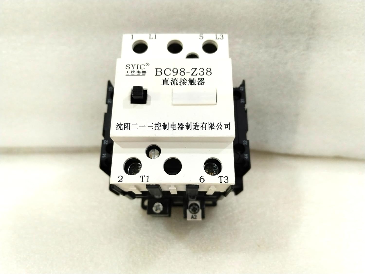
Figure 2.2.3: Top-down view, highlighting the main power terminals and the coil terminals (A1, A2) for control voltage.

Figure 2.2.4: Close-up of the coil voltage indicator, clearly showing "220V DC" for proper electrical connection.

Figure 2.2.5: Side view, illustrating the auxiliary contacts and mounting points of the contactor.
3. Safety Information
Always observe the following safety precautions to prevent personal injury or damage to the equipment:
- Electrical Hazard: Ensure all power is disconnected before installation, wiring, or maintenance. Only qualified personnel should perform electrical work.
- Proper Voltage: Verify that the supply voltage matches the contactor's rated voltage (DC220V). Incorrect voltage can cause severe damage.
- Secure Mounting: Mount the contactor securely in a stable environment to prevent accidental dislodgement.
- Environmental Conditions: Do not expose the contactor to excessive moisture, dust, corrosive gases, or extreme temperatures outside its specified operating range.
- Use as Intended: Use the contactor only for its intended purpose as a DC switching device.
4. Setup and Installation
Follow these steps for proper installation of the BC98-Z38 DC Contactor:
- Unpacking: Carefully remove the contactor from its original packaging. Inspect for any visible damage during transit.
- Mounting: Mount the contactor vertically on a DIN rail or a suitable mounting plate using the designated mounting holes. Ensure it is firmly secured to prevent vibration.
- Wiring - Power Circuit:
- Connect the incoming DC power supply to terminals L1 and L3.
- Connect the load to terminals T1 and T3.
- Ensure all connections are tight and use appropriate wire gauges for the expected current.
- Wiring - Control Circuit:
- Connect the DC220V control voltage to the coil terminals A1 and A2. Observe polarity if specified on the device.
- The coil voltage must match the contactor's rating (DC220V).
- Verification: Before applying power, double-check all wiring connections against your circuit diagram to ensure correctness and safety.
5. Operating Instructions
The BC98-Z38 DC Contactor operates by energizing its coil, which then closes the main contacts, allowing current to flow through the power circuit.
- Power On: Once installation and wiring are complete and verified, apply power to the control circuit.
- Energizing the Coil: When the DC220V control voltage is applied to terminals A1 and A2, the contactor coil will energize. You should hear an audible click as the main contacts close.
- Power Circuit Activation: With the main contacts closed, the DC power from L1/L3 will be connected to T1/T3, supplying power to the connected load.
- De-energizing the Coil: To open the main contacts and disconnect the load, remove the DC220V control voltage from terminals A1 and A2. The contactor will de-energize, and the main contacts will open.
Note: The contactor is designed for continuous operation within its specified ratings. Avoid frequent rapid cycling beyond its design limits, as this can reduce its lifespan.
6. Maintenance
Regular maintenance helps ensure the longevity and reliable operation of your DC contactor. Always disconnect all power before performing any maintenance.
- Visual Inspection: Periodically inspect the contactor for signs of overheating, discoloration, loose connections, or physical damage.
- Terminal Tightness: Check and re-tighten all terminal screws as necessary, especially after initial installation and during routine maintenance checks. Loose connections can lead to overheating and arcing.
- Cleaning: Keep the contactor free from dust and debris. Use a dry, lint-free cloth or compressed air for cleaning. Do not use solvents or abrasive cleaners.
- Contact Wear: While internal contacts are generally not user-serviceable, excessive arcing or contact welding indicates a need for replacement.
7. Troubleshooting
This section provides solutions to common issues you might encounter with the BC98-Z38 DC Contactor.
| Problem | Possible Cause | Solution |
|---|---|---|
| Contactor does not energize (no click) |
|
|
| Contactor energizes but load does not receive power |
|
|
| Contactor hums loudly or overheats |
|
|
8. Specifications
Key technical specifications for the BC98-Z38 DC Contactor:
- Model: BC98-Z38
- Brand: VEICHI
- Coil Voltage: DC220V
- Type: DC Contactor
- Manufacturer: T--E
- Country of Origin: China
- First Available Date: September 17, 2024
9. Support and Contact Information
For technical assistance, inquiries, or support regarding your VEICHI BC98-Z38 DC Contactor, please refer to the seller's contact information or the manufacturer's official support channels.
This product is supplied in original, unused packaging. For any issues related to product defects or performance, please contact your point of purchase.


