1. Introduction
The Radiolink R12F is a 12-channel receiver designed for various RC models, including drones, airplanes, jets, cars, helicopters, fixed-wing aircraft, gliders, multi-rotors, engineering vehicles, racing boats, robots, lawnmowers, and bait boats. It features superior anti-interference capabilities, real-time telemetry, and supports multiple signal output modes (PWM, SBUS, CRSF).
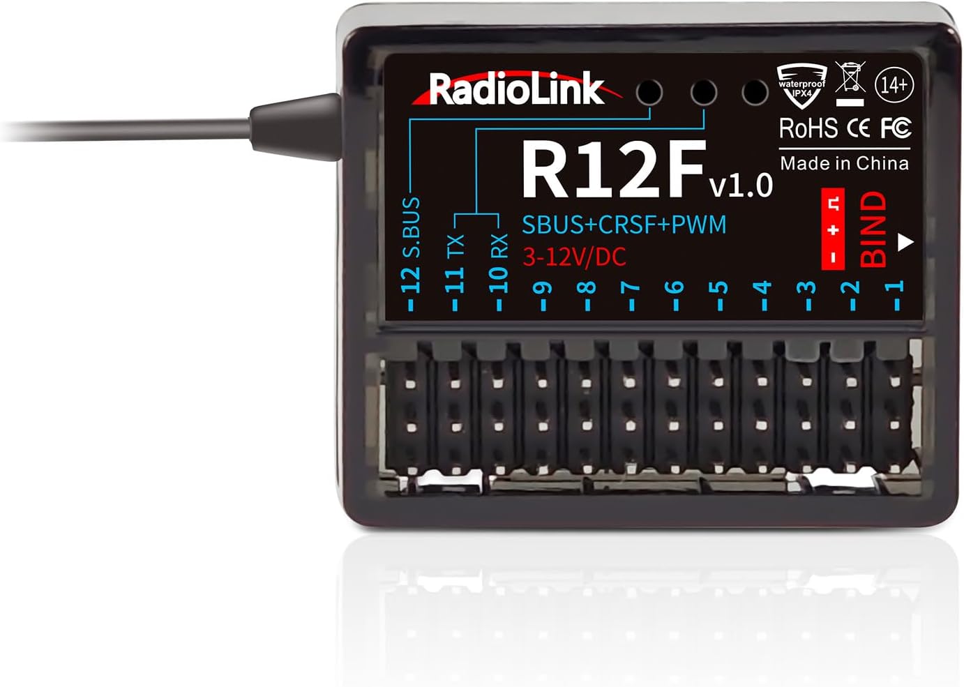
Image 1: Radiolink R12F 12-Channel Receiver. This image displays the compact black receiver unit with its various ports and antenna connection.
2. Key Features
- Superior Anti-Interference: Utilizes a pseudo-random FHSS algorithm for exceptional anti-interference ability, offering a control distance of up to 4000 meters.
- Upgraded Functions: Supports PWM, SBUS, and CRSF signal output modes. The receiver supports online firmware upgrades via a Type-C cable for data transmission.
- Subsidiary ID: Allows designation of a subsidiary ID among multiple bound receivers for specialized applications like long-distance rescue operations with model vehicles.
- Real-time Telemetry: Provides vital information such as battery voltage and RSSI signal in real-time.
- Anti-polarity Connect Protection: Designed to prevent damage to the receiver even if power polarities are mistakenly connected. Supports a wide voltage range (3-12V).
- High Compatibility: Compatible with Radiolink Transmitters including T12D, T16D, RC8X, RC6GS V3, RC4GS V3, T8FB, and T8S.

Image 2: Overview of Radiolink R12F's main features, including signal support, long range, telemetry, protection, subsidiary ID, and online upgrade.
3. Setup
3.1. What's in the Box
- 1x Radiolink R12F Receiver
3.2. Compatible Transmitters
The R12F receiver is compatible with the following Radiolink transmitters:
- T12D
- T16D
- RC8X
- RC6GS V3
- RC4GS V3
- T8FB
- T8S

Image 3: Visual representation of various Radiolink transmitter models compatible with the R12F receiver.
3.3. Binding Method
To bind the R12F receiver to a compatible Radiolink transmitter:
- Ensure the distance between the transmitter and receiver is approximately 60 centimeters.
- Power on the transmitter and the R12F receiver.
- Long press the binding button on the receiver for 3 seconds.
- The LED on the receiver will change from fast flashing to solid, indicating successful binding.
- A signal tower icon should appear on the transmitter screen.

Image 4: Illustration of the binding process for the Radiolink R12F receiver, showing the receiver, a screwdriver pressing the bind button, and a transmitter display indicating signal strength.
4. Operating Modes
4.1. Signal Output Modes
The R12F receiver supports multiple signal output modes:
- PWM Single Signal Output: All 12 channels output PWM signals.
- PWM+SBUS Dual Signal Output: Channels 1-11 output PWM, and Channel 12 outputs SBUS.
- PWM+CRSF Dual Signal Output: Channels 1-9 output PWM, and Channels 10-11 output CRSF. Channel 12 is not used for signal output in this mode.
- PWM+CRSF+SBUS Signal Output: Channels 1-9 output PWM, Channels 10-11 output CRSF, and Channel 12 outputs SBUS.

Image 5: Diagrams illustrating the different signal output configurations (PWM, SBUS, CRSF) available on the R12F receiver ports.
4.2. Subsidiary ID Function
The Subsidiary ID function allows a single transmitter to control specific receivers among multiple bound receivers. This is useful for scenarios requiring selective control, such as long-distance rescue operations with multiple model vehicles.

Image 6: Screenshot from a transmitter showing the Subsidiary ID setting, with examples of its application in controlling specific model vehicles.
5. Maintenance
5.1. Online Firmware Upgrade
The R12F receiver supports online firmware upgrades. Connect the R12F to a computer using a Type-C cable (for data transmission) to easily add the latest functions without requiring additional devices.

Image 7: A Radiolink R12F receiver connected to a laptop via a Type-C cable, illustrating the online upgrade capability.
5.2. Anti-polarity Connect Protection
The receiver is equipped with anti-polarity connect protection. Even if the power polarities are mistakenly connected, the receiver will not be damaged. It supports a wide voltage range of 3-12V, allowing for high voltage servo operation.

Image 8: Wiring diagram demonstrating the anti-polarity connect protection feature, showing various components connected to the receiver.
6. Specifications
| Feature | Detail |
|---|---|
| Item Weight | 0.352 ounces (0.01 Kilograms) |
| Product Dimensions | 1.4 x 0.98 x 0.5 inches |
| Item Model Number | ATA Radiolink R12F A |
| Brand | ATA HOBBY (Radiolink) |
| Color | Black |
| Number of Channels | 12 |
| Special Feature | Long Range |
| Talking Range Maximum | 4000 Meter |
| Voltage | 3-12 Volts (Operating Voltage) |
| Water Resistance Level | Not Water Resistant |
| Manufacturer Recommended Age | 14 years and up |
7. Safety Information
No specific safety information was provided in the product details.
8. Warranty and Support
Specific warranty and support information is not available in the provided product details. Please refer to the manufacturer's official website or contact the seller for details.


