1. Product Overview
The MokerLink 12 Port Gigabit PoE Switch is an unmanaged network switch designed to provide reliable and efficient network connectivity. It features 8 Gigabit PoE+ ports, 2 Gigabit Uplink ports, and 2 SFP ports, offering a total of 12 Gigabit ports. With a 120W power budget, it supports IEEE 802.3af/at standards for powering compatible devices. Key features include AI Detection for stable operation, Quality of Service (QoS) for priority traffic, and an Extend function for enhanced network security and reduced congestion. Its fanless metal design ensures quiet and durable performance.
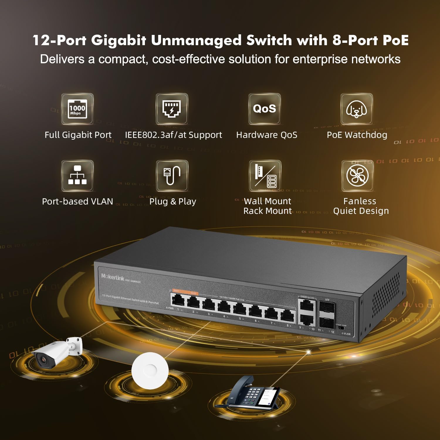
Figure 1.1: Front view of the MokerLink 12 Port Gigabit PoE Switch, illustrating its connectivity with IP cameras, wireless access points, and IP phones.
2. What's in the Box
Upon opening the package, verify that all items are present and in good condition:
- MokerLink 12 Port Gigabit PoE Switch
- Instruction Manual
- Power Cable
- Mount Kit
3. Setup Instructions
3.1 Physical Installation
- Unpack the Switch: Carefully remove the switch and all accessories from the packaging.
- Mounting (Optional): Use the included mount kit to install the switch on a wall or in a rack, if desired. Ensure proper ventilation around the device.
- Connect Power: Connect the provided power cable to the AC input port on the rear of the switch and then to a standard AC power outlet. The power indicator (PWR) on the front panel should illuminate green.
3.2 Network Connection (Plug & Play)
The MokerLink 12 Port Gigabit PoE Switch is a plug-and-play device, requiring no complex configuration for basic operation.
- Connect Non-PoE Devices: For devices that do not require Power over Ethernet (e.g., routers, computers, NVRs), connect them to any of the 8 Gigabit PoE ports (1-8) or the 2 Gigabit Uplink ports (9-10) using standard Ethernet cables.
- Connect PoE Devices: For Power over Ethernet (PoE) compatible devices (e.g., IP cameras, wireless access points, IP phones), connect them to any of the 8 Gigabit PoE ports (1-8). The switch will automatically detect and provide the necessary power (up to 30W per port, 120W total budget) if the device is IEEE 802.3af/at compliant.
- Connect SFP Modules (Optional): Insert compatible SFP modules into the 2 SFP ports (11-12) for fiber optic connections, suitable for long-distance transmission exceeding 100 meters.

Figure 3.1: Illustration of PoE+ power delivery to various devices and data flow for both PoE and non-PoE devices.
4. Operating the Switch
4.1 LED Indicators
The front panel features LED indicators to provide status information:
- PWR (Power Indication): Green light indicates the switch is powered on. No light indicates no power.
- PoE Port 1-8 (Link/Act/PoE): Solid green indicates a stable network link. Blinking green indicates data activity. A separate LED (often amber) indicates PoE power delivery.
- Uplink Port 9-10 (Link/Act): Solid green indicates a stable network link. Blinking green indicates data activity.
- SFP Port 11-12 (Link/Act): Solid green indicates a stable fiber link. Blinking green indicates data activity.
- VLAN (VLAN Indication): Lighting indicates Extend Mode is On. No light indicates Default Mode.

Figure 4.1: Front and rear panel layout with LED indicators and port descriptions.
4.2 AI Detection (PoE Watchdog)
The switch incorporates AI intelligent detection, also known as PoE Watchdog. This feature automatically monitors the data flow on PoE ports. If a connected PoE device becomes unresponsive or disconnected, the switch will automatically restart the corresponding port to restore functionality, ensuring stable operation and reducing the need for manual intervention.

Figure 4.2: PoE Watchdog automatically restarts unresponsive PoE devices.
4.3 QoS (Quality of Service) Function
Ports 1 and 2 support the Quality of Service (QoS) function. This allows you to prioritize network traffic for devices connected to these ports. When network congestion occurs, data from devices on QoS-enabled ports will be prioritized to prevent data loss and ensure critical applications (e.g., video streaming, VoIP) maintain performance.
4.4 Extend Function (Port-based VLAN)
The switch features an EXTEND mode, which enables port-based VLAN functionality. When EXTEND mode is activated via the DIP switch, traffic on PoE Ports 1-8 becomes isolated from each other. These ports will only communicate with the uplink ports (9-12). This isolation helps prevent multicast or broadcast storms from affecting other ports, reduces network congestion, increases bandwidth utilization, and improves overall network security. The VLAN indicator LED will light up when Extend Mode is active.

Figure 4.3: Port-based VLAN isolates traffic between PoE ports.
5. Maintenance
The MokerLink 12 Port Gigabit PoE Switch is designed for low maintenance due to its fanless and durable metal housing.
- Cleaning: Periodically wipe the exterior of the switch with a soft, dry cloth to remove dust. Do not use liquid cleaners or aerosols.
- Ventilation: Ensure that the ventilation holes on the sides of the switch are not obstructed to allow for proper heat dissipation. Although fanless, adequate airflow is important for optimal performance and longevity.
- Environmental Conditions: Operate the switch within the recommended temperature range of -10°C to +55°C. Avoid exposing the device to extreme temperatures, high humidity, or direct sunlight.
- Cable Management: Keep network cables organized and free from kinks or excessive bending to prevent signal degradation.

Figure 5.1: The switch features a fanless design for quiet operation and includes wall/rack mount options.
6. Troubleshooting
If you encounter issues with your MokerLink 12 Port Gigabit PoE Switch, refer to the following common troubleshooting steps:
- No Power:
- Ensure the power cable is securely connected to both the switch and the power outlet.
- Verify that the power outlet is functional.
- Check if the PWR LED on the front panel is illuminated.
- No Network Connectivity:
- Check that Ethernet cables are securely connected to both the switch port and the device.
- Verify that the Link/Act LED for the connected port is illuminated (solid or blinking). If not, try a different cable or port.
- Ensure the connected device is powered on and configured correctly.
- PoE Device Not Receiving Power:
- Confirm that the connected device is PoE compatible (IEEE 802.3af/at standard). This switch does not support passive 24V PoE.
- Check the PoE LED for the specific port.
- Ensure the total power consumption of all connected PoE devices does not exceed the 120W budget.
- The AI Detection (PoE Watchdog) feature should automatically restart unresponsive PoE ports. If a device is still not powering on, try manually disconnecting and reconnecting its Ethernet cable.
- Slow Network Speed:
- Ensure all connected devices and cables support Gigabit Ethernet (1000Mbps).
- Check for excessive network traffic or broadcast storms, especially if Extend mode is not enabled.
- If using QoS, ensure critical devices are connected to ports 1 or 2.
7. Specifications
| Feature | Description |
|---|---|
| Model Number | 12 Gigabit PoE |
| Number of Ports | 12 (8 PoE+, 2 Gigabit Uplink, 2 SFP) |
| Interface Type | PoE+, SFP, RJ45 |
| Data Transfer Rate | 1 Gigabits Per Second (1000Mbps) |
| PoE Standard | IEEE 802.3af/at (Does not support passive 24V PoE) |
| PoE Power Budget | 120W Total, up to 30W per port |
| Switching Capacity | 12Gbps |
| Case Material | Metal |
| Color | Black |
| Item Weight | 3.23 pounds |
| Package Dimensions | 13.94 x 9.65 x 3.62 inches |
| Compatible Devices | IP Camera, Wireless Access Point, Computer Networks, Desktop, Laptop, Printer |
| Included Components | Gigabit PoE switch, Instruction manual, Mount kit, Power cable |
8. Warranty Information
For detailed warranty information, please refer to the warranty card included with your product or visit the official MokerLink website. Keep your purchase receipt as proof of purchase for warranty claims.
9. Customer Support
If you require further assistance or have questions not covered in this manual, please contact MokerLink customer support through their official website or the contact information provided in your product documentation. You can also visit the MokerLink Store on Amazon for additional resources.


