1. Product Overview
The Eletechsup DI-DO CAN/RS485 Relay Controller Module is a versatile IO expansion board designed for industrial automation, CNC machines, and smart home applications. This manual provides detailed instructions for the 16-channel 12V NPN version.
Key Features:
- DC 12V power supply (for this version).
- Low standby current consumption.
- 16 photoelectric isolation input ports (NPN low level active).
- RS485 Interface supporting standard Modbus RTU commands (function codes: write 05/06/15/16, read 01/02/03).
- CAN Interface supporting Standard Frame / Extended Frame Format.
- Hardware reset function and TVS anti-surge protection.
- 16 durable relay outputs.
- Supports up to 64 devices in parallel under MODBUS command mode.
- Configurable RS485 baud rate (9600BPS default, selectable from 2400 to 115200BPS).
- Configurable CAN default baud rate (250Kbps default, settable from 5-1000KBPS).
Package Contents:
- 1PCS DC 12V 16 DI-DO 2 IN 1 CAN/RS485 BUS PLC IO expansion MODULE (with DIN Rail Box).

Figure 1: Eletechsup 16-channel 12V NPN Relay Controller Module with DIN box.
2. Setup and Installation
2.1 Power Supply Connection
Connect a DC 12V power supply to the designated power input terminals on the module. Ensure the correct voltage is applied to prevent damage.
2.2 Bus Interface Connection (CAN/RS485)
The module supports both CAN and RS485 bus interfaces. These can be used simultaneously. Connect the CANL and CANH wires for CAN bus communication, and the RS485 A+ and B- wires for RS485 communication.

Figure 2: Illustration of CAN and RS485 bus connections for multiple modules (CAROA04, CAROB08, CAROC16).
2.3 Input and Output Wiring
The module features 16 opto-isolated NPN digital input ports and 16 relay output ports. Refer to the wiring diagrams below for proper connection of switches and digital signal sources.

Figure 3: Wiring modes for NPN/PNP switches and digital signal sources.
The maximum load for each relay output is 10A at 250VAC, 10A at 125VAC, 10A at 30VDC, 10A at 28VDC, or 10A at 12VDC.
2.4 System Integration Overview
The module can be integrated into various industrial and automation systems, connecting to PLCs, PCs, and other devices via its CAN/RS485 dual bus interface.
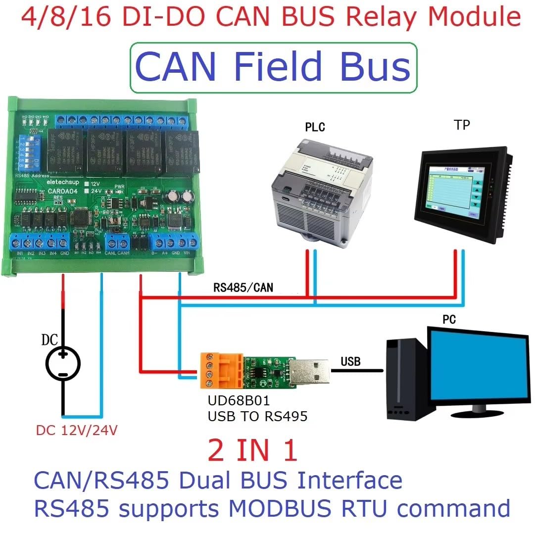
Figure 4: Application diagram illustrating the Eletechsup relay module's integration with a PLC and PC via CAN/RS485 bus.
2.5 DIN Rail Installation
The module is housed in a UM72 DIN rail box, suitable for DIN35 and C45 rail installations. The box is green and made of flame-retardant VO grade material.

Figure 5: Port identification for 4CH, 8CH, and 16CH modules, highlighting RS485 Address (Slave ID), CAN Interface, RS485 Interface, Power Port, and Relay Output Ports.
3. Operating Instructions
3.1 CAN Bus Command Control
To control the module via CAN bus:
- Connect the CANL and CANH wires of the CAN bus to the module.
- Provide 12V power supply to the board.
Factory Settings: Address Code 0x01, Baud Rate 250Kbps.

Figure 6: CAN Command Control Guidelines with connection details.
CAN Command Examples:
Example 1: Set channel 1 to ON and other channels to OFF.
- Send data (HEX): 01 01 81 80 00 00 00 00 00 00
- Return data (HEX): 01 01 81 80 00 00 00 00 00 00
Example 2: Set channels 2, 7, 11, 15 to ON and other channels to OFF.
- Send data (HEX): 01 01 42 44 00 00 00 00 00 00
- Return data (HEX): 01 01 42 44 00 00 00 00 00 00
For detailed CAN protocol information, refer to the "CAROA04 CAROB08 CAROC16 CAN COMMAND" document.
3.2 RS485 Bus Command Control (Modbus RTU)
The RS485 interface supports standard Modbus RTU commands. You can use serial HyperTerminal (serial assistant) or "Modbus Poll" software to send commands.
- Supported function codes: write 05/06/15/16, read 01/02/03.
- Default RS485 baud rate: 9600BPS. Configurable via command to 2400, 4800, 9600, 19200, 38400, 57600, 115200BPS.
- RS485 parity can be set to none, even, or odd.
For detailed RS485 Modbus RTU protocol information, refer to the "CAROA04 CAROB08 CAROC16 RS485 MODBUS RTU COMMAND" document.
Video 1: Demonstration of the Eletechsup 4/8/16 DI-DO CAN Relay Controller Module in operation, showing command input and relay response.
3.3 Input-Output Relationship Modes
The input-output relationship can be configured through instructions to various association modes, including:
- Self-locking (default)
- Interlocking
- Momentary
- Output = Input
4. Specifications
| Feature | Description |
|---|---|
| Power Supply | DC 12V (for 12V version) |
| Standby Current (all relays closed) | 9-14MA |
| Current per active relay | Approx. 29MA additional per relay (e.g., 1 relay open: 41MA, 8 relays open: 226MA) |
| Input Ports | 16 photoelectric isolation inputs (NPN low level active) |
| Output Ports | 16 relay outputs |
| Max Load per Relay | 10A / 250VAC, 10A / 125VAC, 10A / 30VDC, 10A / 28VDC, 10A / 12VDC |
| RS485 Interface | Modbus RTU command support (write 05/06/15/16, read 01/02/03) |
| RS485 Baud Rate | Default 9600BPS (Configurable: 2400, 4800, 9600, 19200, 38400, 57600, 115200BPS) |
| RS485 Parity | None, Even, Odd |
| CAN Interface | Standard Frame / Extended Frame Format support |
| CAN Baud Rate | Default 250Kbps (Configurable: 5-1000KBPS) |
| Data Sending/Returning Time | Configurable, max 1000ms |
| Protection | Hardware reset, TVS anti-surge protection |
| Dimensions (16DI-16DO with Din Rail Box) | 255 * 82 * 40mm |
| Weight (16DI-16DO with Din Rail Box) | 410g |
| DIN Rail Box Model | UM72 |
| DIN Rail Box Color | Green |
| DIN Rail Box Insulation Grade | Flame-retardant VO grade |
| DIN Rail Box Installation | DIN35 and C45 rail |
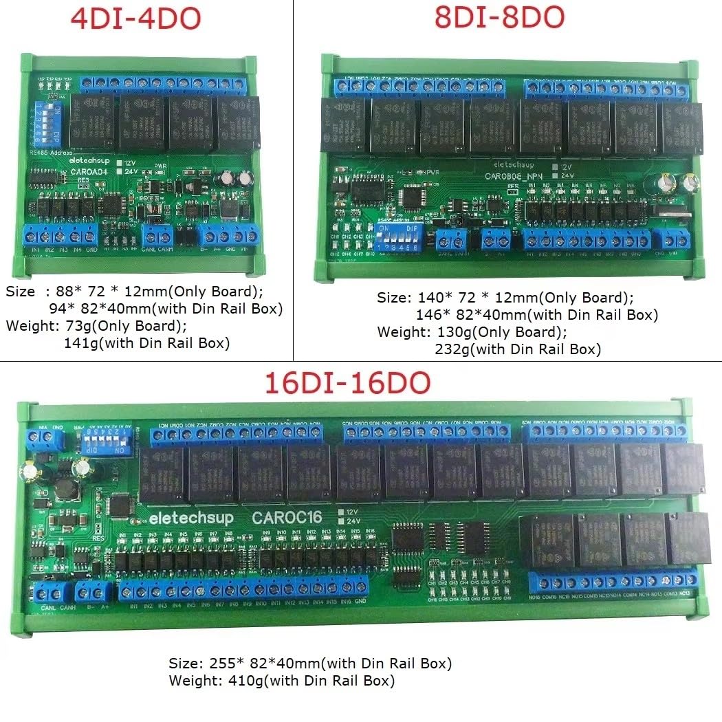
Figure 7: Dimensions and weights for 4-channel, 8-channel, and 16-channel modules, both board-only and with DIN rail box.
5. Troubleshooting
This section provides general troubleshooting tips. For specific issues, refer to the detailed protocol documents for CAN and RS485.
- No Power: Ensure the 12V DC power supply is correctly connected and providing the specified voltage. Check for loose connections.
- Communication Issues (CAN/RS485):
- Verify bus wiring (CANL/CANH, RS485 A+/B-).
- Confirm baud rates match between the module and the master device.
- Check address codes for conflicts in multi-device setups.
- Ensure proper termination resistors are used on the bus if required by your network topology.
- Relay Not Activating:
- Verify the input signal is correctly applied (NPN low level active).
- Check the command sent to the module for correct channel selection and state.
- Ensure the load connected to the relay is within the specified maximum load limits.
- Unexpected Behavior: Perform a hardware reset if the module is unresponsive. Review the input-output relationship mode settings.
6. Maintenance
The Eletechsup Relay Controller Module is designed for reliable operation with minimal maintenance. Follow these guidelines:
- Cleaning: Keep the module free from dust and debris. Use a soft, dry cloth for cleaning. Avoid using liquids or abrasive cleaners.
- Environmental Conditions: Ensure the module operates within its specified environmental conditions (temperature, humidity) to prolong its lifespan.
- Connection Integrity: Periodically check all wiring connections for tightness and signs of wear or corrosion, especially in industrial environments.
- Firmware Updates: If firmware updates become available, follow the manufacturer's instructions carefully.
7. Warranty and Support
Specific warranty information is not provided in the product description. For warranty details, technical support, or further inquiries, please contact Eletechsup directly through their official channels or the retailer from whom the product was purchased.
Additional resources and detailed protocol documents ("CAROA04 CAROB08 CAROC16 CAN COMMAND" and "CAROA04 CAROB08 CAROC16 RS485 MODBUS RTU COMMAND") can be obtained by contacting the manufacturer.


