1. Introduction
This manual provides detailed instructions for the installation, operation, and maintenance of your MokerLink 6-Port 10Gbps Managed Switch. This device is designed to enhance network performance with its high-speed connectivity and Layer 2 management capabilities. Please read this manual thoroughly before using the product to ensure proper setup and functionality.
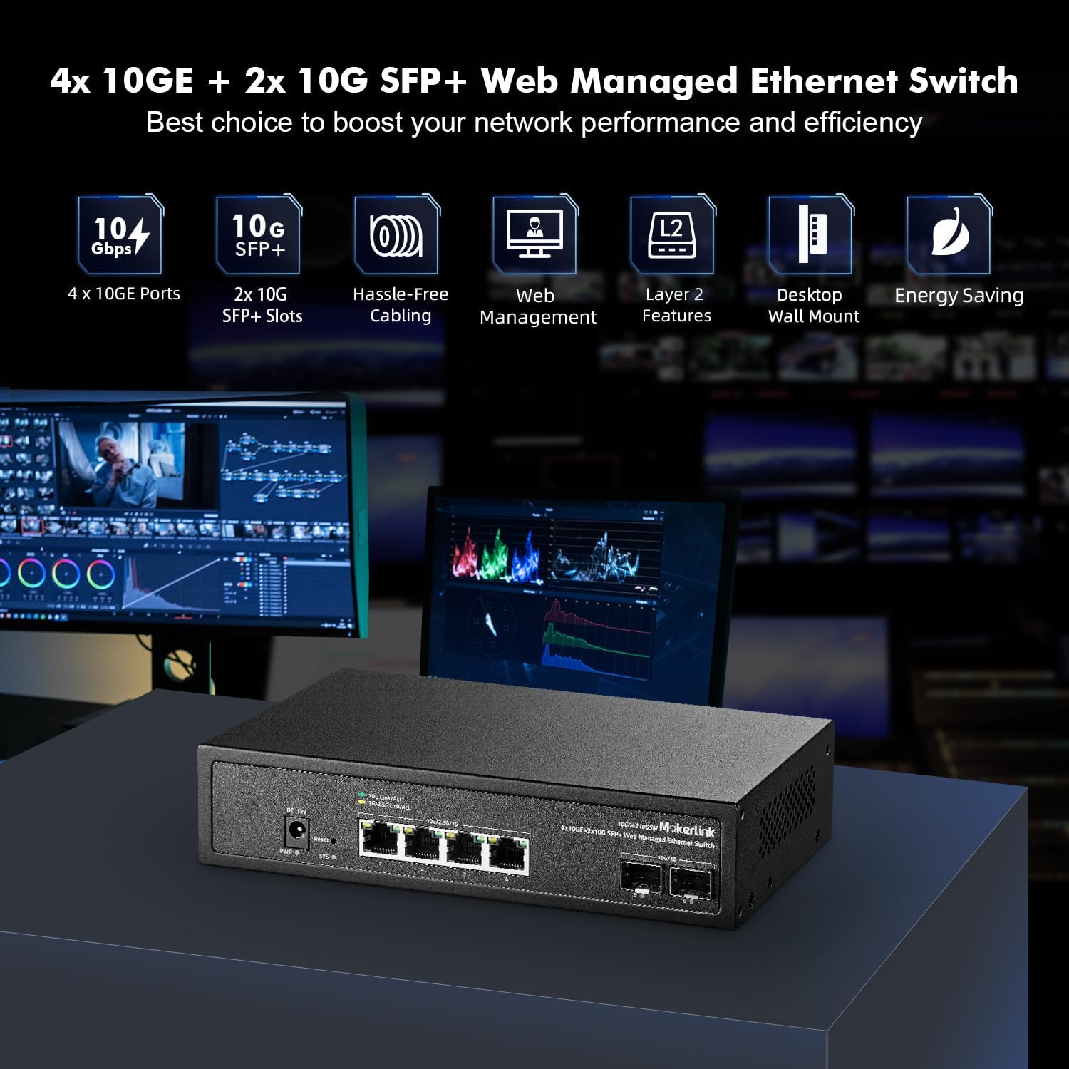
Image 1.1: MokerLink 6-Port 10Gbps Managed Switch overview, highlighting 4x 10GE ports, 2x 10G SFP+ slots, web management, Layer 2 features, desktop/wall mount capability, and energy saving.
2. Product Overview
2.1 Key Features
- High-Speed Ports: Equipped with 4x 10Gbps Ethernet RJ45 ports supporting 10G/5G/2.5G/1000M/100M auto-negotiation, and 2x 10Gbps SFP+ ports compatible with 1G/10G optical fiber modules.
- L2 Web Management: Supports comprehensive Layer 2 management features including QoS, ACL, Link Aggregation (LACP), loop detection, VLAN configuration, IP-MAC-VLAN Port Binding, Port Mirroring/Isolation/Rate-limit/Security, Storm Control, Spanning Tree, diagnosis/Ping, SNMP, and device/port status query.
- High Bandwidth: Offers a switching capacity of 120Gbps, ensuring non-blocking 10G line speed forwarding across all ports.
- Open SFP+ Slots: Compatible with standard SFP optical modules (multi-mode, single-mode, SFP to RJ45 modules) without encryption. SFP modules are not included by default.
- Durable Design: Features a metal case and an industrial-grade fan for efficient heat dissipation and stable operation.
- Versatile Application: Suitable for use as a core, distribution, or access layer switch in various home and commercial network environments.
2.2 Port Configuration and Indicators
The switch features a clear layout of ports and LED indicators for easy monitoring and management.

Image 2.1: Front panel layout showing 4x 10Gbps RJ45 ports, 2x 10Gbps SFP+ ports, power input, reset button, and LED indicators for power, system status, and port activity.
- PWR (Power Indicator):
- Lighting On: Power is supplied.
- Un-light: No power.
- SYS (System Indicator):
- On: The system is operating normally.
- Flashing: System startup in progress.
- 10Gbps RJ45 Port Indicators:
- Yellow: 100/1000Mbps/2.5Gbps link speed.
- Green: 10Gbps link speed.
- Flashing: Data transmitting.
- Off: Link blocked.
- 10Gbps SFP+ Port Indicators:
- Yellow: 100/1000Mbps/2.5Gbps link speed.
- Green: 10Gbps link speed.
- Flashing: Data transmitting.
- Off: Link blocked.
- Reset Button: Short press to restart. Press and hold for 5 seconds to restore factory settings.
3. Setup
3.1 Package Contents
Verify that your package contains the following items:
- MokerLink 10G Switch (Model: 4*10G Eth,2*10G SFP Managed)
- Power Adapter
- User Manual (this document)
- Mounting accessories (if applicable for desktop/wall mount)
Note: SFP+ modules are not included by default and must be purchased separately if required.
3.2 Physical Installation
- Placement: Place the switch on a stable, flat surface or mount it to a wall using appropriate hardware. Ensure adequate ventilation around the device to prevent overheating. Avoid placing it near heat sources or in direct sunlight.
- Power Connection: Connect the provided power adapter to the DC 12V input port on the switch and then plug the adapter into a standard electrical outlet. The PWR LED should illuminate.
- Network Connections:
- RJ45 Ports: Connect your network devices (e.g., servers, workstations, NAS, routers) to the 10Gbps RJ45 ports using Cat5e, Cat6, Cat6a, or Cat7 Ethernet cables. For 10Gbps speeds, Cat6a or Cat7 cables are recommended.
- SFP+ Ports: Insert compatible 1G or 10G SFP+ optical modules into the SFP+ slots. Then, connect fiber optic cables from the SFP+ modules to your fiber-enabled network devices.

Image 3.1: The switch connected to a router, laptop, gaming PC, NAS, and 4K/8K video devices, demonstrating its role in a high-performance network.
4. Operating the Switch
4.1 Initial Access to Web Management Interface
The MokerLink Managed Switch can be configured and monitored via a web-based graphical user interface (GUI).
- Ensure your computer is connected to one of the switch's RJ45 ports.
- Configure your computer's IP address to be in the same subnet as the switch's default IP address (e.g., if the switch's default IP is 192.168.2.1, set your computer's IP to 192.168.2.X, where X is not 1, and subnet mask to 255.255.255.0).
- Open a web browser (e.g., Chrome, Firefox) and enter the default IP address of the switch: 192.168.2.1
- When prompted, enter the default login credentials:
- User Name: admin
- Password: admin
- Upon successful login, you will access the switch's web management interface. It is highly recommended to change the default password for security reasons.

Image 4.1: The web management interface, showing system information and configuration options. Default IP: 192.168.2.1, User Name: admin, Password: admin.
4.2 Layer 2 Management Features
The switch offers a suite of Layer 2 features to optimize network performance and security.

Image 4.2: Overview of powerful L2 software features including IGMP, Mirroring, LACP, Multicast, STP/RSTP, ERPS, VLAN, QoS, Trunk, MAC Constraint, Jumbo Frame, ACL, and Backup/Upgrade.
4.2.1 VLAN (Virtual Local Area Network)
VLANs allow you to logically segment your network into smaller broadcast domains, improving security and performance. The switch supports 802.1Q Tag-based VLANs.

Image 4.3: Illustration of 802.1Q Tag-based VLANs, segregating network traffic for different devices (e.g., cameras, Wi-Fi, phones) without separate physical equipment.
4.2.2 QoS (Quality of Service)
QoS prioritizes network traffic to ensure critical applications (like voice or video) receive sufficient bandwidth, reducing packet loss and latency.

Image 4.4: QoS prioritizing audio, video, and data traffic with high, medium, and low priority levels respectively.
4.2.3 Link Aggregation (LACP)
Link Aggregation Control Protocol (LACP) bundles multiple physical links into a single logical link, increasing bandwidth and providing redundancy.

Image 4.5: Link Aggregation (LACP) connecting the MokerLink switch to another switch and a NAS device, enhancing bandwidth and resilience.
4.2.4 Loop Detection
The loop detection feature helps identify and prevent network loops, which can cause broadcast storms and network instability.

Image 4.6: Loop Detection mechanism preventing network slowdowns or traffic stoppage caused by accidental network loops between switches.
5. Maintenance
5.1 Firmware Updates
Periodically check the MokerLink official website for firmware updates. Firmware updates can provide new features, performance improvements, and security patches. Follow the instructions provided with the firmware update package carefully. Typically, firmware updates are performed through the web management interface.
5.2 Cleaning
To maintain optimal performance, keep the switch clean.
- Power off the device and disconnect it from the power source before cleaning.
- Use a soft, dry cloth to wipe the exterior of the switch.
- Use compressed air to gently clear dust from ventilation openings and ports.
- Do not use liquid cleaners or aerosol sprays.
5.3 Heat Dissipation
The switch is equipped with an industrial-grade fan for heat dissipation. Ensure that the ventilation openings are not blocked to allow for proper airflow. While the fan is designed for efficient cooling, some noise is normal. Maintaining good airflow is crucial for the longevity and stable operation of the device.
6. Troubleshooting
This section addresses common issues you might encounter with your MokerLink switch.
6.1 No Power
- Ensure the power adapter is securely connected to both the switch and a working electrical outlet.
- Verify that the power outlet is functional by plugging in another device.
- Check the PWR LED on the switch. If it is off, there might be a power issue.
6.2 No Link on a Port
- Check the Ethernet or SFP+ cable connection. Ensure it is securely plugged into both the switch port and the connected device.
- Verify that the cable type is appropriate for the speed (e.g., Cat6a/Cat7 for 10Gbps RJ45).
- Ensure the connected device is powered on and functioning correctly.
- Check the port's LED indicator. If it's off, there's no link. If it's flashing, data is transmitting.
- For SFP+ ports, ensure the SFP+ module is correctly inserted and compatible.
- Try a different port or cable to rule out a faulty component.
6.3 Cannot Access Web Management Interface
- Confirm your computer's IP address is in the same subnet as the switch's IP (default: 192.168.2.1).
- Ensure you are using the correct default IP address, username (admin), and password (admin).
- Clear your browser's cache or try a different browser.
- Temporarily disable any firewall or antivirus software on your computer that might be blocking access.
- If the IP address was changed and forgotten, you may need to perform a factory reset using the reset button (press and hold for 5 seconds). Warning: A factory reset will erase all custom configurations.
6.4 Excessive Fan Noise
- Ensure the switch is placed in an environment with good airflow and not in an enclosed space.
- Check for any obstructions around the fan vents.
- While the fan is industrial-grade, some noise is normal. If the noise is unusually loud or changes significantly, contact MokerLink support.
7. Specifications
| Feature | Description |
|---|---|
| Model Number | 4*10G Eth,2*10G SFP Managed |
| Number of Ports | 6 (4x 10Gbps RJ45, 2x 10Gbps SFP+) |
| Interface Type | RJ45, SFP+ |
| Data Transfer Rate | 10 Gigabits Per Second (per port) |
| Switching Capacity | 120Gbps |
| Packet Forwarding Rate | 89.28Mpps |
| MAC Address Table Size | 16K |
| Case Material | Metal |
| Upper Temperature Rating | 55 Degrees Celsius |
| Item Weight | 2.02 pounds |
| Package Dimensions | 12.17 x 7.72 x 2.4 inches |
| Included Components | 10G Switch, Power Adapter |
| Compatible Devices | Desktop, Laptop, Printer, Servers, NAS, Routers |
8. Warranty and Support
8.1 Warranty Information
MokerLink products typically come with a standard manufacturer's warranty. For specific details regarding the warranty period and terms for your device, please refer to the warranty card included in your product packaging or visit the official MokerLink website. Keep your purchase receipt as proof of purchase for warranty claims.
8.2 Technical Support
If you encounter any issues that cannot be resolved using this manual, or if you require further assistance, please contact MokerLink technical support.
- Website: Visit the official MokerLink website for support resources, FAQs, and contact information.
- Email/Phone: Refer to your product packaging or the MokerLink website for specific email addresses or phone numbers for technical support.
When contacting support, please have your product model number (4*10G Eth,2*10G SFP Managed) and purchase information ready.


