1. Introduction
The AYWHP ESP32 Development Board is a versatile module designed for Internet of Things (IoT) applications, compatible with various development environments like Arduino IDE, Lua, and MicroPython. It integrates an ESP32 chip with dual-mode Bluetooth and WiFi capabilities, making it suitable for a wide range of connected projects.
This board features a CP2012 USB-to-serial chip for reliable communication and a Type-C interface for modern connectivity. Its compact design and 38 GPIO pins offer extensive flexibility for connecting sensors, actuators, and other peripherals.
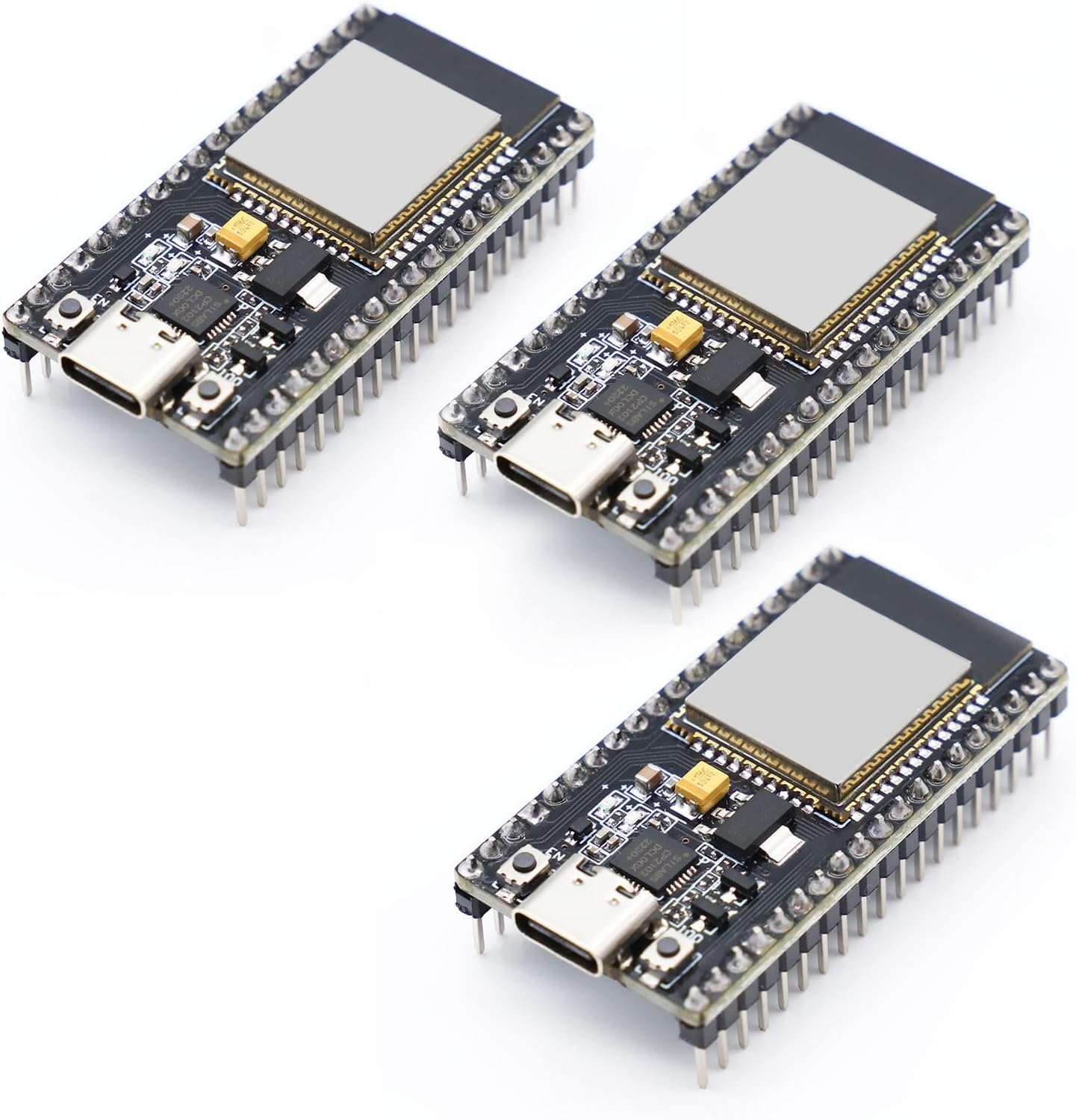
Figure 1: Front view of the AYWHP ESP32 Development Board.
Video 1: Overview of the ESP32-DevKitC-32 Development Board modules.
2. What's in the Box
Each package contains the following items:
- 3 x ESP32 Development Board
3. Setup
3.1 Physical Connection
To begin using your ESP32 Development Board, connect it to your computer using a USB Type-C cable. The board is equipped with a CP2012 USB-to-serial chip, which facilitates communication between the board and your computer.

Figure 2: ESP32 Development Board connected to a breadboard for prototyping.
3.2 Driver Installation
Depending on your operating system, you may need to install drivers for the CP2012 chip. These drivers are typically available from the Silicon Labs website. Once installed, your computer should recognize the ESP32 board as a serial port.
3.3 Integrated Development Environment (IDE) Setup
The ESP32 board is compatible with several development environments, including Arduino IDE, Lua, and MicroPython. For Arduino IDE, you will need to add the ESP32 board support package. For MicroPython or Lua, you will need to flash the respective firmware onto the board.
Video 2: Demonstration of the ESP32 Development Board in a basic setup with an OLED display.
4. Operating the ESP32 Board
4.1 Programming and Firmware Upload
After setting up your chosen IDE, you can write and upload code to the ESP32 board. For Arduino IDE, select the correct board and COM port, then click 'Upload'. For MicroPython or Lua, use the appropriate tools to flash the firmware and then upload your scripts.

Figure 3: Pinout diagram of the ESP32 Development Board.
4.2 WiFi and Bluetooth Modes
The ESP32 supports three main operational modes for wireless communication:
- STA (Station) Mode: The ESP32 connects to an existing WiFi network, acting as a client device.
- AP (Access Point) Mode: The ESP32 creates its own WiFi network, allowing other devices to connect to it.
- STA+AP Coexistence Mode: The ESP32 operates as both a station and an access point simultaneously.
These modes provide flexibility for various network configurations in your projects.
Video 3: Demonstration of programming and flashing firmware to an ESP32 WROOM Development Board.
5. Maintenance
To ensure the longevity and optimal performance of your ESP32 Development Board, follow these maintenance guidelines:
- Handle with Care: Avoid dropping the board or subjecting it to physical shock.
- Keep Dry: Protect the board from moisture and liquids.
- Cleanliness: Keep the board free from dust and debris. Use a soft, dry brush or compressed air for cleaning.
- Static Discharge: Always handle the board in an anti-static environment to prevent damage from electrostatic discharge.
- Proper Storage: When not in use, store the board in an anti-static bag or a protective container.
6. Troubleshooting
If you encounter issues with your ESP32 Development Board, consider the following troubleshooting steps:
- Connection Issues: Ensure the USB Type-C cable is securely connected to both the board and your computer. Verify that the CP2012 drivers are correctly installed. Try a different USB port or cable.
- Firmware Upload Failure: Check if the correct board and COM port are selected in your IDE. Ensure the board is in bootloader mode (often by holding the 'BOOT' button while connecting or resetting). Verify your code for syntax errors.
- No Power/LED Indicator: Confirm that the USB cable is providing power. Check for any visible damage to the board.
- WiFi/Bluetooth Connectivity Problems: Ensure your code correctly initializes and configures the WiFi or Bluetooth module. Check for interference from other wireless devices.
- Unexpected Behavior: Review your code for logical errors. Test individual components or sections of your code to isolate the problem.
7. Specifications
Below are the technical specifications for the ESP32 Development Board:

Figure 4: Dimensions of the ESP32 Development Board.
| Feature | Detail |
|---|---|
| Chip | ESP32 (with dual-core LX6 microprocessor) |
| Main Frequency | 240MHz |
| Memory | 4MB Flash |
| WiFi Standard | IEEE 802.11 b/g/n |
| Bluetooth Version | Bluetooth 4.2 and BLE (Low Power Bluetooth) |
| I/O Ports | 32 GPIO pins in total |
| Operating Voltage | 3.3V |
| Input Voltage Range | 5V (via Type-C port) or 7-12V (via VIN pin) |
| Power Supply Interface | Type-C interface or VIN pin |
| Dimensions | Approx. 50mm x 25.4mm |
| Development Environment | Compatible with Arduino IDE, Lua, MicroPython |
8. Warranty and Support
For warranty information and technical support, please refer to the product packaging or contact the manufacturer directly. Keep your proof of purchase for any warranty claims.