1. Product Overview
The AYWHP ESP-32-S3 Development Board, equipped with the ESP-1-N16R8 module, is a high-performance platform designed for AIoT (Artificial Intelligence of Things) and Arduino-compatible projects. This board integrates a low-power Microcontroller Unit (MCU) System-on-Chip (SoC) with 2.4 GHz Wi-Fi and Bluetooth LE dual-mode wireless communication capabilities.
Key features include:
- Low-power Performance: Integrates 2.4 GHz Wi-Fi and Bluetooth 5 (LE) dual-mode communication, suitable for IoT applications requiring efficient power usage.
- Simplified Programming and Debugging: Facilitates easy programming and firmware burning via dual USB Type-C ports, supporting both USB and UART modes.
- Multiple Power Saving Modes: Supports various low-power modes configurable for different application scenarios to optimize battery life.
- Dual Download Modes: Offers flexibility with both direct USB connection download and USB-to-serial port download options.
- Diverse Connectivity: Provides dual-mode Wi-Fi and Bluetooth 5.0 (LE) connectivity, making it ideal for a wide range of smart devices and IoT applications.
The product package includes 5 AYWHP ESP-32-S3 Development Boards with the ESP-1-N16R8 module.
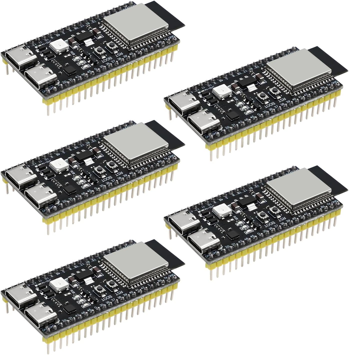
Image 1.1: Overview of the AYWHP ESP-32-S3 Development Boards.
2. Technical Specifications
The following table details the technical specifications of the ESP-32-S3 Development Board:
| Parameter | Value |
|---|---|
| Microcontroller | ESP-32-S3 |
| Chip | ESP-1-N16R8 |
| CPU | Dual-core Xtensa 32-bit LX7 |
| Clock Speed | Up to 240 MHz |
| Flash Memory | 16 MB (embedded) |
| RAM | 512 KB |
| Wireless Connectivity | Wi-Fi 802.11 b/g/n, Bluetooth 5.0 (BLE) |
| I/O Pins | 34 GPIOs |
| Analog-to-Digital Converter (ADC) | 12-bit resolution, 18 channels |
| Digital-to-Analog Converter (DAC) | 8-bit resolution |
| UART Interfaces | 3 |
| SPI Interfaces | 2 |
| I2C Interfaces | 2 |
| PWM Channels | 16 |
| Operating Voltage | 3.3V |
| Power Supply | USB-C or external 5V supply |
| USB Interface | USB-UART bridge for programming and debugging |
| Item Model Number | YY1-0163 |
| Operating System Compatibility | Linux (and other common development environments) |
| Item Weight | 2.08 ounces |
| Package Dimensions | 7.09 x 5.12 x 1.26 inches |
3. Hardware Overview
This section provides a detailed look at the physical components and layout of the ESP-32-S3 Development Board.
3.1. Block Diagram

Image 3.1: Block diagram illustrating the internal architecture and connections of the DevKitC-1 module, including the USB-to-UART bridge, LDO, N16R8 module, RGB LED, and header blocks.
3.2. Pinout Diagram

Image 3.2: Detailed pinout diagram for the DevkitM-1 module, showing GPIO assignments, power pins (3V3, 5V, GND), and special function pins like JTAG, ADC, and serial communication interfaces.
3.3. Hardware Components and Features

Image 3.3: Labeled diagram highlighting key hardware components such as the N16R8 Module, Power Chip, Integrated RGB-LED Module, RST Button, BOOT Button, PWR LED, TX LED, RX LED, USB to Serial Port Chip (CH343P), and S3 Pass-Through Type-C USB & OTG ports.

Image 3.4: Close-up views of the Type-C USB ports, Power Supply Chip, and the N16R8 Module, providing a detailed look at these critical components.
3.4. Dimensions
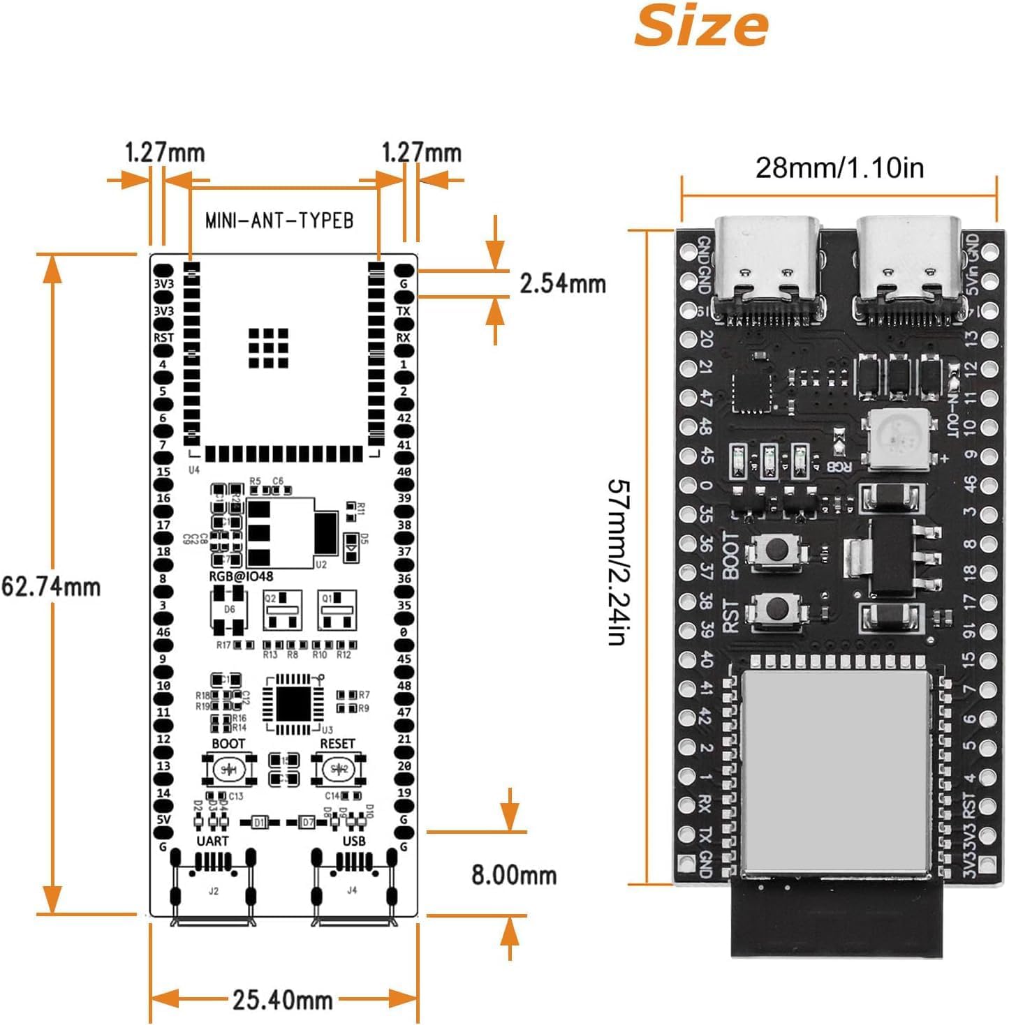
Image 3.5: Diagram showing the physical dimensions of the development board in millimeters and inches, including pin spacing and overall board size.
3.5. Front and Back Views

Image 3.6: Front and back views of the development board, illustrating component placement on both sides and the USB-OTG port on the back.
4. Initial Setup
To begin using your AYWHP ESP-32-S3 Development Board, follow these general setup steps:
- Driver Installation: Connect the board to your computer using a USB-C cable. Your operating system may automatically install necessary drivers. If not, you may need to manually install drivers for the CH343P USB-to-Serial chip. Refer to the chip manufacturer's website for the latest drivers.
- Integrated Development Environment (IDE) Setup: Install your preferred IDE, such as Arduino IDE or PlatformIO for VS Code.
- Board Support Package: Within your IDE, install the ESP32 board support package. For Arduino IDE, this typically involves adding the Espressif ESP32 board manager URL in preferences and then installing the ESP32 boards. For PlatformIO, ensure the Espressif 32 platform is installed.
- Select Board: Choose the appropriate ESP32-S3 board from the IDE's board manager.
- Connect Power: The board can be powered via the USB-C port or an external 5V supply. Ensure the power source is stable.
5. Basic Operation
Once the board is set up, you can upload and run your code:
- Connect: Plug the ESP-32-S3 board into your computer using a USB-C cable.
- Select Port: In your IDE, select the correct serial port (COM port on Windows, /dev/ttyUSBx or /dev/cu.usbserial-xxxx on Linux/macOS) corresponding to the board's USB-to-UART bridge.
- Upload Code: Write or open your desired program (sketch) in the IDE and click the upload button. The IDE will compile the code and upload it to the board.
- Monitor Output: Use the serial monitor in your IDE to view output from your program, if applicable.
6. Programming and Debugging
The ESP-32-S3 Development Board offers flexible programming and debugging options:
- Dual USB Type-C Ports: The board features two USB Type-C ports. One typically functions as a USB-UART bridge for serial communication and programming, while the other can be used for direct USB (CDC) communication or OTG functionalities.
- Download Modes: The board supports both direct USB download and USB-to-serial port download. For direct USB programming, ensure that USB CDC on boot is enabled in your build flags if using PlatformIO or similar environments.
- RGB LED: The integrated RGB LED is typically connected to GPIO48. To ensure it functions correctly, verify that any associated jumper pads on the board are properly connected. Some boards may require a solder bridge on a specific jumper for the RGB LED to operate.
- Boot and Reset Buttons: The BOOT button is used to put the ESP32-S3 into download mode, often pressed while pressing and releasing the RST button. The RST button resets the microcontroller.
7. Power Management
The ESP-32-S3 is designed for low-power applications and supports various power-saving modes. These modes can be configured in your firmware to reduce power consumption based on the application's requirements, extending battery life for portable projects. Consult the Espressif documentation for detailed information on configuring deep sleep, light sleep, and other power management features.
8. Troubleshooting Common Issues
If you encounter issues with your ESP-32-S3 Development Board, consider the following:
- Programming Port Selection: Ensure you are selecting the correct USB port in your IDE for uploading code. Often, there are two USB-C ports; one is for USB-to-UART communication (typically labeled 'UART' or 'COM' in device manager), and the other might be for native USB. For programming, the USB-UART bridge port is usually the correct choice. Avoid using the native USB port for initial code uploads unless specifically configured for it.
- RGB LED Not Lighting Up: The onboard RGB LED is commonly connected to GPIO48. If it does not light up, verify that your code is targeting GPIO48. Additionally, check for a small jumper pad on the board near the RGB LED; some boards require this jumper to be closed (e.g., with a solder blob) for the LED to function.
- Upload Failures: If code upload fails, try the following:
- Ensure correct board and port are selected in the IDE.
- Press and hold the BOOT button, then briefly press and release the RST button, then release the BOOT button to enter download mode before attempting to upload.
- Verify USB cable integrity and try a different cable or USB port on your computer.
- Check for correct driver installation.
- No Serial Output: Confirm the baud rate in your serial monitor matches the baud rate set in your code (e.g., 115200).
9. Care and Maintenance
To ensure the longevity and optimal performance of your ESP-32-S3 Development Board:
- Handle with Care: Avoid dropping the board or subjecting it to excessive physical stress.
- Static Electricity: Always handle the board in an anti-static environment to prevent damage from electrostatic discharge.
- Power Supply: Use a stable and appropriate power supply (3.3V or 5V via USB-C). Do not exceed the maximum voltage ratings.
- Storage: Store the board in a dry, cool environment, away from direct sunlight and extreme temperatures.
- Cleaning: If necessary, gently clean the board with a soft, dry brush or compressed air. Avoid using liquids or harsh chemicals.
10. Warranty and Support
For specific warranty information, please refer to the documentation provided at the time of purchase or contact AYWHP customer support directly. Technical assistance and further resources may be available through the manufacturer's official website or community forums dedicated to ESP32 development.


