1. Introduction
This manual provides detailed instructions for the safe and effective use of the Boartechs 400W 15A DC-DC Step-Up Boost Converter Module. This module is designed to convert a lower DC input voltage to a higher DC output voltage, offering constant current and constant voltage regulation. It is suitable for various applications, including battery charging and driving high-power LEDs.
2. Safety Information
- Always ensure proper insulation and ventilation to prevent overheating.
- Do not exceed the maximum input voltage (50V) or output current (15A).
- Observe correct polarity for input and output connections. Incorrect polarity can damage the module and connected devices.
- Handle with care to avoid electrostatic discharge (ESD) damage.
- Keep away from moisture and conductive materials.
- Installation and adjustments should only be performed by qualified personnel.
3. Product Overview
The Boartechs 400W 15A DC-DC Step-Up Boost Converter Module is a high-efficiency power conversion unit. It features robust heat sinks for thermal management, an inductor coil, capacitors, and potentiometers for voltage and current adjustment.
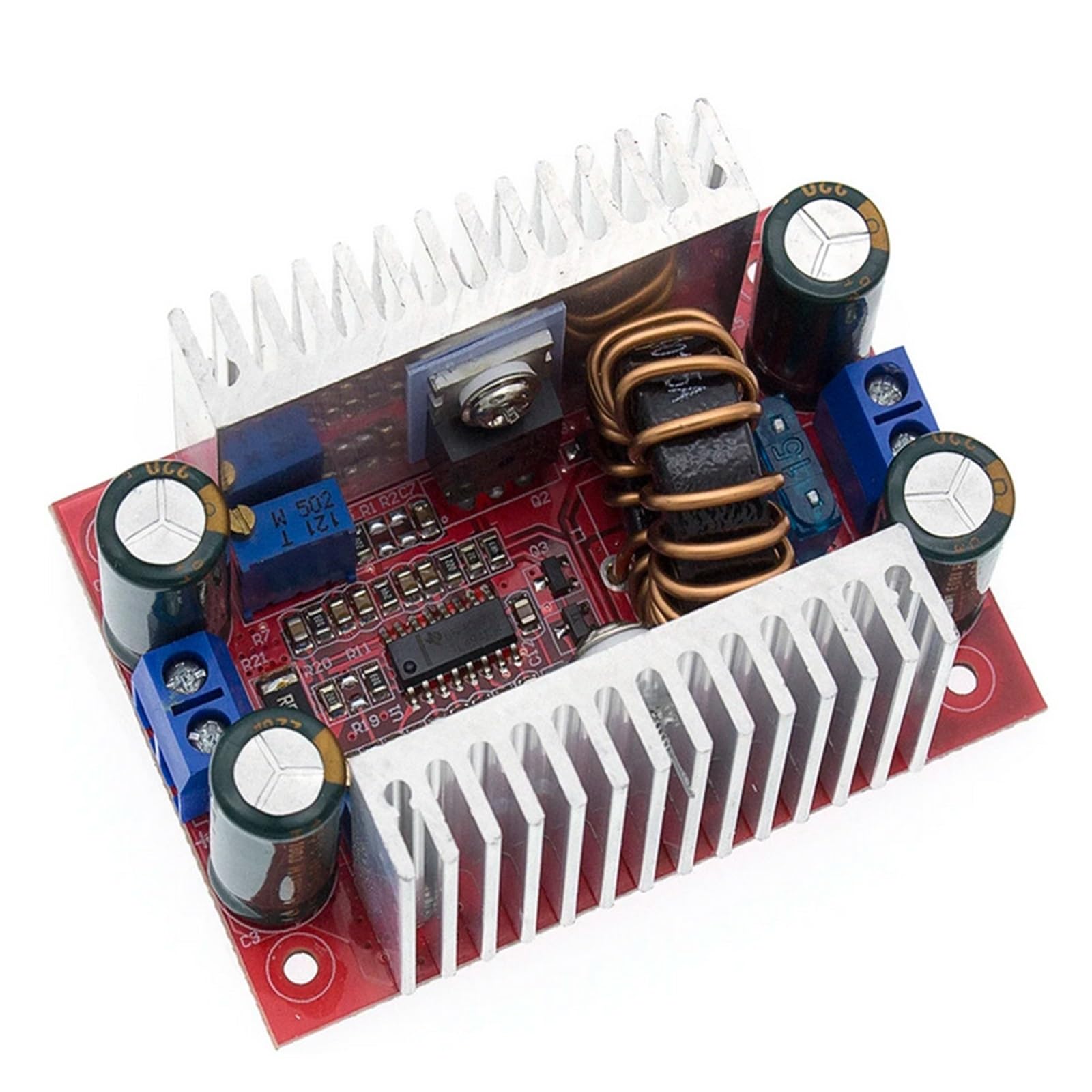
An overhead view of the Boartechs 400W 15A DC-DC Step-Up Boost Converter Module, showing the red PCB, large inductor coil, heat sinks on both sides, input/output terminals, and adjustment potentiometers.
4. Specifications
| Parameter | Value |
|---|---|
| Input Voltage | 8.5V - 50V DC |
| Output Voltage | 10V - 60V DC (Adjustable) |
| Output Current | 0.2A - 15A (Adjustable, Max) |
| Output Power | 400W (Max) |
| Conversion Efficiency | Up to 96% (Efficiency depends on input/output voltage, current, and voltage difference) |
| Operating Temperature | -40°C to +85°C (If ambient temperature exceeds 40°C, please reduce power or enhance heat dissipation) |
| Operating Frequency | 150KHz |
| Protection Features | Over-temperature protection, Current limiting protection, Short-circuit protection (output short circuit will not burn out the module) |
| Dimensions | Approximately 1.18 x 0.79 x 0.39 inches (Package Dimensions) |
| Weight | Approximately 3.53 ounces (100 grams) |
5. Setup
- Input Connection: Connect the DC input voltage source (8.5V to 50V) to the "IN+" (positive) and "IN-" (negative) terminals. Ensure correct polarity.
- Output Connection: Connect your load or battery to the "OUT+" (positive) and "OUT-" (negative) terminals. Ensure correct polarity.
- Voltage Adjustment: Use the "V-ADJ" potentiometer (usually marked with a 'V' or 'CV') to set the desired output voltage. Turn clockwise to increase voltage, counter-clockwise to decrease.
- Current Adjustment: Use the "I-ADJ" potentiometer (usually marked with an 'I' or 'CC') to set the desired output current limit. Turn clockwise to increase current, counter-clockwise to decrease. This is crucial for constant current applications like battery charging.
- Heat Dissipation: For continuous high-power operation (above 250W or high ambient temperatures), ensure adequate airflow or additional cooling measures are in place. The integrated heat sinks help, but external cooling may be necessary.
Note: When adjusting voltage or current, it is recommended to use a multimeter to accurately measure the output values.
6. Operating Instructions
6.1. As a Step-Up Voltage Converter (Constant Voltage Mode)
- Connect the input and output as described in the Setup section.
- Adjust the "V-ADJ" potentiometer to achieve the desired output voltage.
- Ensure the "I-ADJ" potentiometer is set to its maximum (fully clockwise) if you do not require current limiting, or set it to a value higher than your expected load current.
- The module will maintain the set output voltage as long as the input voltage is within range and the output current does not exceed the set limit or the module's maximum capacity.
6.2. As a Battery Charger (Constant Current/Constant Voltage Mode)
- Connect the input power supply to the module and the battery to be charged to the output terminals.
- Set Float Voltage (CV): Without connecting the battery, adjust the "V-ADJ" potentiometer to the desired float voltage for your battery type (e.g., 4.2V for a single Li-ion cell, 14.4V for a 12V lead-acid battery).
- Set Charge Current (CC): Connect an ammeter in series with the output, or short the output terminals (briefly and carefully, ensuring the current limit is set low initially). Adjust the "I-ADJ" potentiometer to the desired charging current. For safety, start with a low current and increase gradually.
- Once both voltage and current limits are set, connect the battery. The module will charge the battery at the set constant current until the battery voltage reaches the set float voltage, then it will switch to constant voltage mode.
6.3. As a High Power Constant Current Regulator Drive Module
- This mode is ideal for driving high-power LEDs or other loads that require a stable current.
- Connect the input and the LED load to the output.
- Adjust the "V-ADJ" potentiometer to a voltage slightly higher than the forward voltage of your LED string.
- Adjust the "I-ADJ" potentiometer to the desired operating current for your LEDs. The module will then supply a constant current to the LEDs.
7. Maintenance
- Keep the module clean and free from dust and debris.
- Periodically inspect all connections to ensure they are secure.
- Ensure adequate ventilation, especially during prolonged high-power operation.
- Do not attempt to modify the module, as this may void any implied warranty and could lead to damage or injury.
8. Troubleshooting
- No Output Voltage:
- Check input voltage and polarity.
- Ensure the "V-ADJ" potentiometer is not set to its minimum.
- Verify connections to the load.
- Output Voltage Too Low/Unstable:
- Input voltage may be too low or unstable.
- Load current may exceed the set current limit or module's capacity.
- Check for overheating; reduce load or improve cooling.
- Output Current Not Reaching Desired Level:
- Adjust the "I-ADJ" potentiometer clockwise to increase the current limit.
- Ensure the load resistance is not too high for the set voltage.
- Input power supply may not be able to provide sufficient current.
- Module Overheating:
- Reduce the output power (voltage or current).
- Improve ventilation or add active cooling (fan).
- Ensure the input/output voltage difference is not excessively large at high currents, as this increases heat generation.
9. Warranty and Support
This product is covered by a standard manufacturer's warranty against defects in materials and workmanship. For warranty claims or technical support, please contact your retailer or the manufacturer directly. Please retain your proof of purchase.


