
1. Product Overview
The BN-LINK Pool Pump Timer is a robust and versatile digital timer designed for controlling high-power electrical devices such as pool pumps, water heaters, and fans. Its heavy-duty construction and weatherproof design make it ideal for both indoor and outdoor applications. With 7-day programmability and multiple ON/OFF settings, it offers precise control and energy savings.

Figure 1: BN-LINK Pool Pump Timer, front view with cover open.
Key Features:
- Heavy Duty Capacity: 40A Resistive, 1HP to 2HP, 120-277 VAC.
- Programmable: Up to 8 ON/OFF settings per day, 7-day programmable.
- Versatile Modes: AUTO Mode, Always ON, Always OFF.
- Weatherproof: Suitable for indoor and outdoor use, operating temperature range from -40°F to 130°F.
- Manual Override: Convenient manual switch for temporary control.

Figure 2: Labeled components of the timer's control panel.
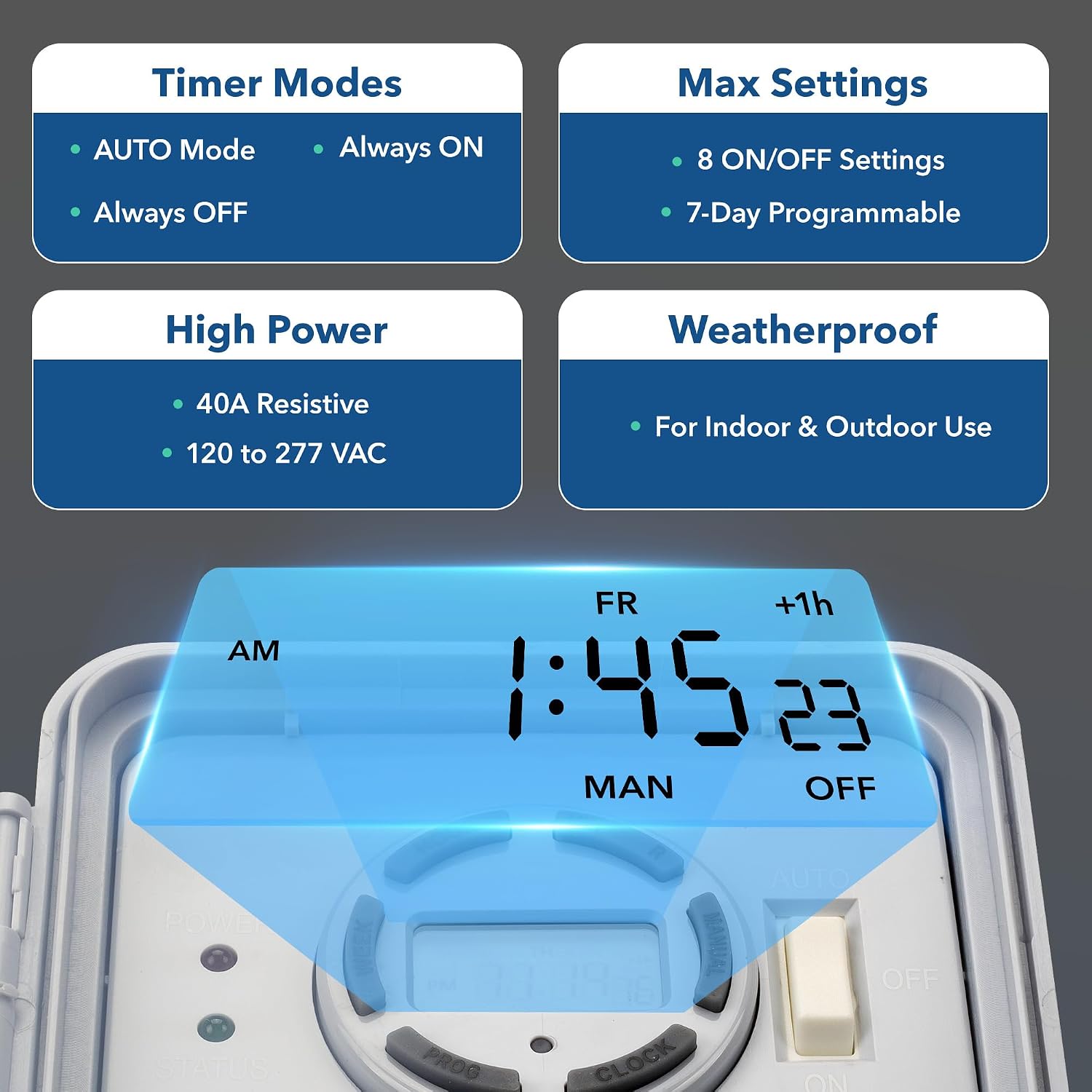
Figure 3: Summary of key timer features.
2. Safety Information
Please read and understand all safety instructions before installation and operation. Failure to follow these instructions may result in electric shock, fire, or serious injury.
- DANGER: Risk of electric shock. Disconnect power at the circuit breaker or fuse box before installing or servicing.
- Installation should be performed by a qualified electrician in accordance with all local and national electrical codes.
- Ensure the timer's voltage and amperage ratings match your application's requirements.
- Do not immerse the timer in water.
- Keep the timer's cover securely closed to maintain its weatherproof rating.
3. Installation
The timer is designed for wall mounting. Ensure the mounting surface is stable and can support the weight of the timer and associated wiring. Refer to the following diagrams for typical wiring configurations.
Mounting:
- Select a suitable location, preferably near the appliance to be controlled, away from direct sunlight if possible, but within its operating temperature range.
- Use appropriate screws and anchors for your mounting surface. The timer features mounting holes for secure attachment.
- Dimensions: Approximately 8.86 inches (H) x 7.08 inches (W) x 2.71 inches (D).

Figure 4: Timer dimensions and mounting features.
Wiring Diagrams:
Always ensure power is disconnected before performing any wiring. Consult a qualified electrician if you are unsure about any wiring procedures.

Figure 5: Typical SPDT Wiring Diagrams.

Figure 6: Typical DPDT Wiring Diagrams.
4. Setup
Before applying power, set the current time and program your desired ON/OFF cycles.
Setting Current Time:
- Press the CLOCK button.
- While holding CLOCK, press WEEK to set the current day of the week.
- While holding CLOCK, press HOUR to set the current hour.
- While holding CLOCK, press MIN to set the current minute.


Figure 7: Buttons for setting current time.
Programming ON/OFF Cycles:
The timer allows up to 8 ON/OFF programs. Each program consists of an ON time and an OFF time.
- Press the PROG button to enter programming mode. The display will show '1 ON'.
- Press WEEK to select the day(s) for this program (e.g., Mon-Fri, Sat-Sun, everyday, specific days).
- Press HOUR and MIN to set the desired ON time.
- Press PROG again. The display will show '1 OFF'.
- Press WEEK to select the day(s) for this OFF program (should match the ON program).
- Press HOUR and MIN to set the desired OFF time.
- Repeat steps 1-6 for additional programs (up to 8).
- Press CLOCK to exit programming mode and return to the current time display.

Figure 8: PROG button for programming cycles.
Daylight Saving Time Adjustment:
To adjust for Daylight Saving Time, press the R button (often labeled +1h) to advance the time by one hour. Press it again to revert.

Figure 9: +1h button for Daylight Saving Time.
5. Operating Modes
The timer offers three main operating modes controlled by the side switch and a manual override button.
Mode Switch (Side):
- AUTO: The timer operates according to the programmed ON/OFF cycles. This is the standard operating mode.
- ON: The connected device will remain continuously ON, overriding all programmed cycles.
- OFF: The connected device will remain continuously OFF, overriding all programmed cycles.
Manual Override Button:
The MANUAL button allows for temporary override of the current program without affecting the stored settings. Pressing it will toggle the output state (ON to OFF, or OFF to ON) until the next programmed event occurs.

Figure 10: MANUAL button for temporary override.
6. Maintenance
The BN-LINK Pool Pump Timer is designed for minimal maintenance. Regular inspection can help ensure long-term performance.
- Cleaning: Wipe the exterior with a soft, damp cloth. Do not use abrasive cleaners or solvents. Ensure the cover is closed and sealed before cleaning.
- Inspection: Periodically check the wiring connections for tightness and signs of corrosion. Ensure the timer's housing is free from cracks or damage that could compromise its weatherproof integrity.
- Battery (Internal): The timer has an internal battery to retain settings during power outages. This battery is typically long-lasting and not user-replaceable.

Figure 11: Timer's weatherproof design in an outdoor setting.
7. Troubleshooting
If you encounter issues with your BN-LINK Pool Pump Timer, refer to the following common problems and solutions.
| Problem | Possible Cause | Solution |
|---|---|---|
| Timer display is blank or not responding. | No power supply; internal battery depleted. | Check circuit breaker/fuse. Ensure proper wiring. If power is present, allow time for internal battery to charge (if applicable). |
| Timer does not turn ON/OFF at programmed times. | Incorrect programming; timer in ON/OFF mode; current time is incorrect. | Verify programmed ON/OFF times and days. Ensure the side switch is set to 'AUTO'. Correct the current time if necessary. |
| Minute button or other control buttons are unresponsive. | Unit defect; temporary software glitch. | Try resetting the timer (if a reset button is available, otherwise disconnect power for a few minutes). If the issue persists, contact customer support. |
| Device remains ON/OFF continuously. | Side switch set to 'ON' or 'OFF'; manual override engaged. | Ensure the side switch is set to 'AUTO'. Press the 'MANUAL' button to disengage manual override. |
| Timer is difficult to install or wire. | Complex wiring requirements; lack of electrical experience. | Refer to the wiring diagrams in Section 3. If unsure, consult a qualified electrician. |
If these steps do not resolve the issue, please contact BN-LINK customer support for further assistance.
8. Specifications
| Attribute | Value |
|---|---|
| Model Number | CP-U49B |
| Voltage | 120, 240, 277 VAC |
| Max Amperage | 40A Resistive |
| Horsepower (HP) Rating | 1HP (120VAC), 2HP (208-227VAC), 1HP (277VAC) |
| Programmability | 7-Day, up to 8 ON/OFF programs |
| Operating Temperature | -40°F to 130°F (-40°C to 54°C) |
| Dimensions (Approx.) | 9.13 x 7.48 x 3.23 inches (Package) |
| Item Weight | 1.7 pounds |
| Certifications | ETL Listed |
| UPC | 810079586592 |
9. Warranty and Support
BN-LINK products are manufactured to high-quality standards. For warranty information, technical support, or to report any issues, please contact BN-LINK customer service directly.
- Refer to the product packaging or the official BN-LINK website for the most current contact information and warranty details.
- Keep your purchase receipt as proof of purchase for warranty claims.