1. Introduction
The PNI CH2000R PRO Gold is an advanced access control system designed specifically for hotel environments. This system provides secure and convenient access for guests and staff using EM proximity cards. Its robust construction and intelligent features ensure reliable operation and enhanced security for hotel rooms. This manual provides essential information for the proper installation, operation, and maintenance of your PNI CH2000R PRO Gold access control system.
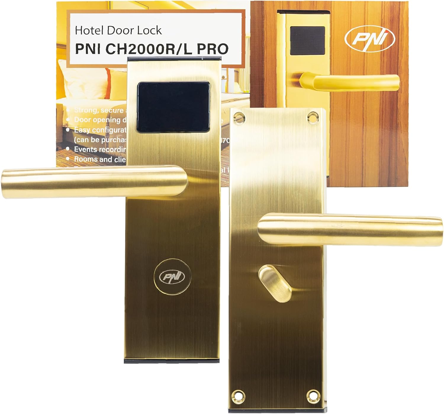
Figure 1: PNI CH2000R PRO Gold Hotel Access Control System with its packaging, showing the front view of the lock and the card reader.
2. Safety Information
- Read all instructions carefully before installation and use.
- Ensure the product is installed by qualified personnel to prevent damage or malfunction.
- Do not expose the lock to extreme temperatures, humidity, or corrosive environments.
- Use only the specified battery type (4 x AA alkaline batteries). Do not mix old and new batteries or different battery types.
- Keep mechanical keys in a secure location, separate from the lock, for emergency access.
- Avoid using abrasive cleaners or solvents on the lock surface.
3. Package Contents
Verify that all components are present in the package before beginning installation:
- Access control unit (front and rear panels with handles)
- Mortise lock body
- Strike plate and strike box
- Installation accessories (screws, spindle)
- Mechanical keys (2-3 pieces)
- Battery pack holder
- Installation and use manual (this document)
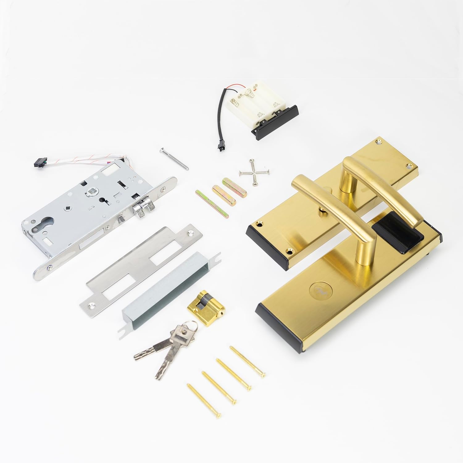
Figure 2: All components included in the package, such as the lock panels, mortise, battery pack, keys, and various screws.
4. Setup and Installation
The PNI CH2000R PRO Gold is designed for right-side opening doors. Detailed installation steps are provided in the separate installation manual included with the product. Below are general guidelines:
- Prepare the Door: Ensure the door thickness is between 30mm and 50mm. Mark and drill holes according to the provided template for the mortise lock, spindle, and mounting screws.
- Install Mortise Lock: Insert the mortise lock body into the prepared cavity on the door edge and secure it with screws.
- Install Front Panel: Connect the wiring from the front panel (with card reader) to the mortise lock. Position the front panel on the door, ensuring the spindle aligns correctly.
- Install Rear Panel: Connect the wiring from the rear panel to the front panel and the mortise lock. Position the rear panel on the door, aligning the spindle and securing it with mounting screws.
- Install Batteries: Open the battery compartment on the rear panel. Insert 4 new AA alkaline batteries, ensuring correct polarity. Close the compartment.
- Install Strike Plate and Box: Install the strike plate and box on the door frame, ensuring proper alignment with the mortise latch and deadbolt.
- Software Configuration (Optional but Recommended): For full functionality, the lock requires configuration using dedicated software (PNI FLH70, purchased separately). This software allows for card programming, event recording, and room management.

Figure 3: Internal view of the lock's components, including the circuit board, wiring connections, and the battery compartment, illustrating the complexity of the internal structure.

Figure 4: The main components of the lock system, including the front handle assembly with card reader, the mortise lock mechanism, and the rear handle assembly with the thumb turn.
5. Operating Instructions
5.1. Opening with an EM Card
- Present a valid EM proximity card (T5557/Mifare compatible) to the card reader area on the front panel.
- The lock will emit a confirmation sound and/or light indicator if the card is valid.
- Within a few seconds, push down the handle to open the door.
- The door will automatically lock after closing.
5.2. Opening with a Mechanical Key
In case of emergency or battery failure, the lock can be opened using the mechanical key:
- Insert the mechanical key into the keyhole located on the front panel.
- Turn the key to unlock the mechanism.
- Push down the handle to open the door.
5.3. "Do Not Disturb" Function
When the thumb turn on the inside handle is engaged, the "Do Not Disturb" function is activated, preventing external card access. Only mechanical keys can override this function.
5.4. Event Recording
The lock records access events, which can be downloaded and reviewed using the dedicated management software (PNI FLH70).

Figure 5: A detailed view of the rear handle, showing the thumb turn mechanism used for privacy and internal locking.
6. Maintenance
6.1. Battery Replacement
The lock is powered by 4 AA alkaline batteries, providing approximately 10,000 openings. When the battery level is low, the lock will provide a low voltage alarm. Replace all 4 batteries promptly when this occurs to ensure continuous operation.
- Locate the battery compartment on the rear panel of the lock.
- Open the compartment cover.
- Remove the old batteries and dispose of them responsibly.
- Insert 4 new AA alkaline batteries, ensuring correct polarity (+/-).
- Close the battery compartment cover securely.
6.2. Cleaning
Clean the lock surface with a soft, dry cloth. For stubborn marks, a slightly damp cloth can be used, followed by drying. Do not use abrasive cleaners, solvents, or harsh chemicals, as these can damage the zinc alloy finish.
7. Troubleshooting
- Lock does not respond to card:
- Ensure the card is valid and correctly programmed for the lock.
- Check if the "Do Not Disturb" function is active from the inside.
- Replace batteries if a low voltage alarm has been indicated.
- Try using a mechanical key to confirm the lock mechanism is not jammed.
- Low Voltage Alarm: The lock will indicate low battery power. Replace all 4 AA alkaline batteries immediately.
- False Closing Alarm: If the door is not fully closed, the lock may issue a false closing alarm. Ensure the door is properly shut and the latch engages fully.
- Open Door Warning: If the door remains open for an extended period, the lock may issue a warning. Close the door to clear the warning.
- Lock mechanism feels stiff: Apply a small amount of graphite lubricant to the mortise lock mechanism. Do not use oil-based lubricants.
8. Specifications
| Feature | Specification |
|---|---|
| Model Number | PNI-CH20RG-PRO |
| Part Number | PNI-CH20RG-PRO |
| Material | Zinc Alloy |
| Color | Gold |
| Product Dimensions (L x W x H) | 6 x 24 x 7.5 cm |
| Item Weight | 2.24 kg |
| Power Supply | 6V (4 x AA Alkaline Batteries) |
| Max Consumption | 200 mA |
| Card Compatibility | T5557 / Mifare |
| Card Reading Distance | 0 - 5 cm |
| Recommended Door Thickness | 30 ~ 50 mm |
| Door Opening Direction | Right |
| Operating Temperature | -26°C ~ +80°C |
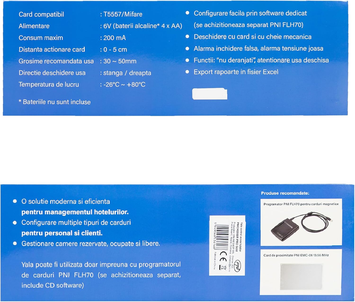
Figure 6: Product specifications and features as displayed on the packaging, confirming technical details.
9. Warranty and Support
For warranty information and technical support, please refer to the documentation provided at the time of purchase or contact your local PNI distributor. Ensure you have your product model number (PNI-CH20RG-PRO) and purchase details available when seeking support.


