1. Introduction
This manual provides comprehensive instructions for setting up, operating, and maintaining your AYWHP LoRa V3 Development Board. The board integrates WiFi, LoRa, and Bluetooth connectivity, powered by a dual-core SX1262 CP2102 chip, and features a 0.96-inch OLED display for real-time information. It is designed for various IoT applications and supports Arduino development.
2. Safety Information
Handle the development board with care to avoid electrostatic discharge. Do not expose the device to extreme temperatures, moisture, or corrosive environments. Ensure proper power supply connections to prevent damage. Always disconnect power before making any wiring changes.
3. Package Contents
Verify that all items are present in your package:
- 1 x LoRa Development Board
- 1 x LoRa Antenna
- 1 x SH1.25X2P male cable (15cm)
- 2 x Pin Headers

Image: Contents of the LoRa V3 Development Board package, showing the main board, antenna, connecting cable, and pin headers.
4. Product Overview
The AYWHP LoRa V3 Development Board is a versatile single-board computer designed for IoT projects. Key features include:
- Integrated Connectivity: Features WiFi, LoRa, and Bluetooth for diverse network connections, including a special 2.4GHz metal spring antenna.
- Ease of Use: Reserved IPEX (U.FL) interface for LoRa and an integrated CP2102 USB to serial port chip for convenient program downloading and debugging.
- Arduino Compatibility: Supports Arduino development and the LoRaWAN protocol, allowing communication with any LoRaWAN gateway.
- 0.96-inch OLED Display: Equipped with an OLED display to show debugging information, battery status, and other data.
- Wide Applications: Suitable for smart cities, farms, industrial control, home security, wireless metering, and various IoT development projects due to its robust RF design and low-power consumption.

Image: The AYWHP LoRa V3 Development Board, showcasing its compact design, OLED display, USB-C port, and included accessories.
Component Identification

Image: Detailed view of the LoRa V3 Development Board with key components labeled for easy identification, such as the OLED display, USB-C port, antennas, and various buttons and interfaces.
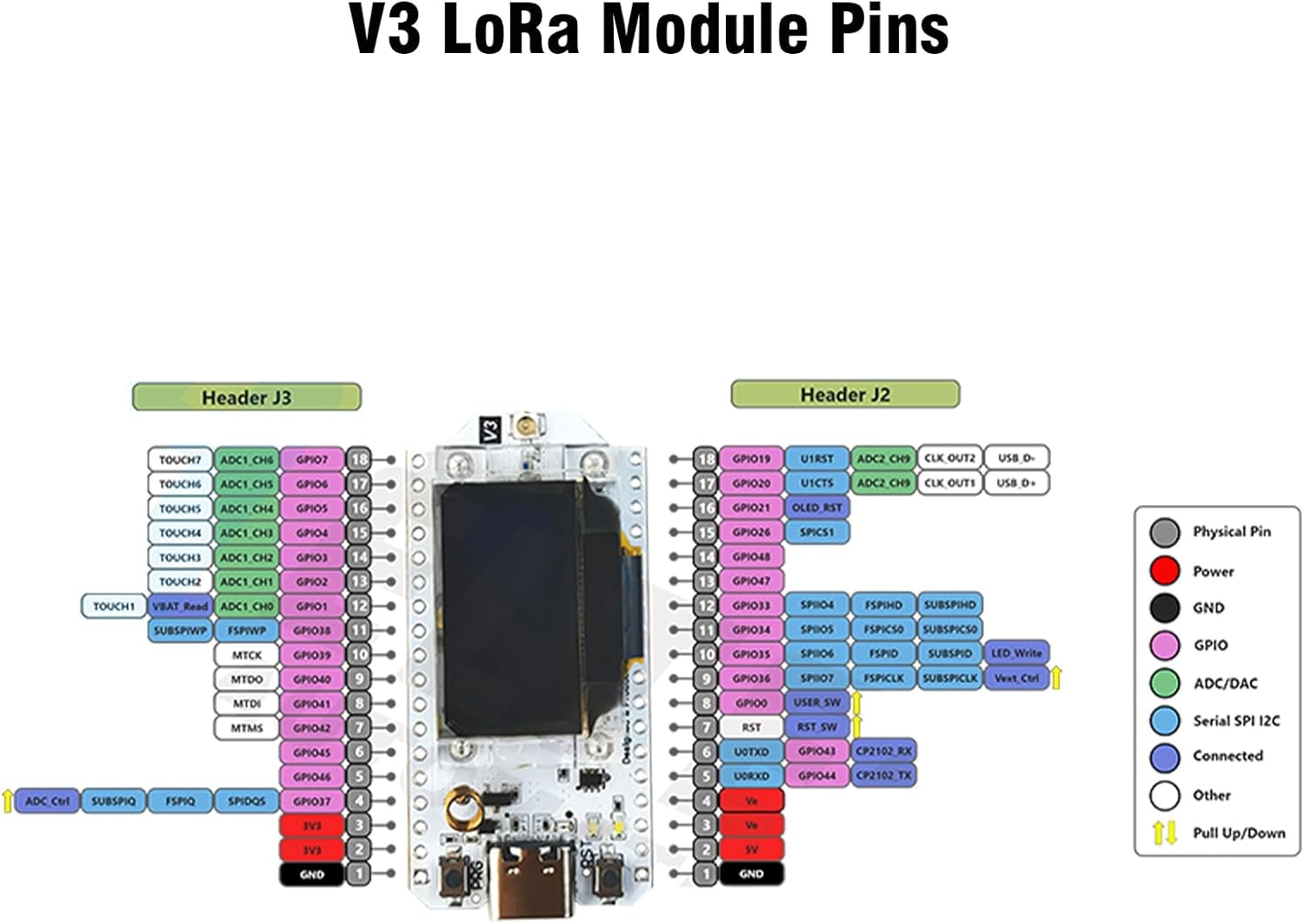
Image: Comprehensive pinout diagram for the V3 LoRa Module, detailing the functions of each pin on Header J2 and Header J3, including GPIO, power, ground, and communication interfaces.
5. Getting Started
5.1. Installation Steps
- Install the development environment:
Download and install the Arduino IDE. Add the development board support package to the Arduino IDE by adding an additional board URL in Preferences. Install the LoRa library (e.g., Arduino-LoRa). - Connect the device:
Connect the development board to your computer using a USB cable. Select the development board model as 'Dev Module' and choose the correct serial port in the Arduino IDE. - Programming and Testing:
Select example code (e.g., 'LoRa Send' or 'LoRa Receive') from the Arduino IDE. Configure the frequency to 868MHz or 915MHz, depending on regional specifications. Upload the code to the board and monitor the serial port output for testing. - OLED Display Use:
Utilize the U8g2 or Adafruit_SSD1306 library to control the integrated 0.96-inch OLED display. - External Sensor Connection:
Connect sensors via I2C, UART, or GPIO interfaces as required by your project.
5.2. Assembly and Initial Setup
The following video demonstrates the assembly process and initial setup for the LoRa V3 Development Board, including connecting the antenna and battery.
Video: A step-by-step guide on how to use and assemble the LoRa V3 Development Board, including connecting the antenna and battery, and flashing firmware.
6. Operating Instructions
Once the development environment is set up and the code is uploaded, the board will operate according to the programmed logic. The OLED display will show relevant information such as debugging messages, battery status, or data being transmitted/received.
LoRa Communication Demonstration
This video demonstrates the LoRa communication capabilities of the ESP32 LoRa V3 Board, showing how data is transmitted and received between devices.
Video: Demonstration of LoRa communication using the ESP32 LoRa V3 Board, illustrating data exchange between two units.
7. Maintenance
Keep the board clean and free from dust and debris. Avoid physical impact or excessive force on the components. Store in a dry environment when not in use. Regularly check connections for any signs of wear or damage.
8. Troubleshooting
- Board not recognized by Arduino IDE: Ensure the USB cable is properly connected and the correct serial port is selected. Reinstall CP2102 drivers if necessary.
- LoRa communication issues: Verify frequency settings match between sender and receiver. Check antenna connections. Ensure LoRa library is correctly installed and configured.
- OLED display not working: Confirm the correct display library (U8g2 or Adafruit_SSD1306) is installed and initialized in your code. Check I2C connections.
- Power issues: Ensure the board is receiving adequate power via USB or battery. Check battery connections if applicable.
9. Specifications
| Feature | Detail |
|---|---|
| Processor | 240 MHz (Espressif) |
| RAM | LPDDR4 |
| Series | V3 |
| Operating System | Linux |
| Item Weight | 1.13 ounces |
| Package Dimensions | 4.13 x 3.58 x 0.98 inches |
| Connectivity Technology | WiFi, LoRa, Bluetooth |
| Included Components | LoRa Development Board |

Image: Detailed hardware specifications of the LoRa V3 Development Board, including frequency, flash memory, processor, WiFi support modes, development environment, working voltage, main control chip, LoRa chip support frequency band, operating range temperature, open communication distance, UDP continuous throughput, computing power, USB interface chip, and dual-mode Bluetooth.
10. Warranty and Support
For warranty information and technical support, please refer to the manufacturer's official website or contact your retailer. Keep your purchase receipt for warranty claims.


