1. Introduction
This manual provides detailed instructions for the installation, operation, and maintenance of your Sodola 10Gb L2 Managed PoE Switch. This device is designed to facilitate high-speed data transfer and efficient power delivery over Ethernet, suitable for various networking environments.
The switch features 4 x 10G PoE ports, 1 x 10G RJ-45 uplink port, and 1 x 10G SFP+ port. It supports advanced Layer 2 management functionalities and adheres to IEEE802.3af/at/bt PoE standards.

Image 1.1: Front view of the Sodola 10Gb L2 Managed PoE Switch.
2. Product Overview
2.1. Package Contents
- Sodola 10Gb L2 Managed PoE Switch (Model: 4X10G POE+10G RJ45+SFP+)
- Power Adapter/Cable
- User Manual
2.2. Hardware Features

Image 2.1: Front and rear panel overview of the switch, highlighting ports and indicators.
The switch features a robust metal casing and an efficient cooling system. Key components include:
- Ports:
- 4 x 10G PoE Ports (10GBase-T)
- 1 x 10G RJ-45 Uplink Port (10GBase-T)
- 1 x 10G SFP+ Port
- 1 x Console Port (RJ45)
- LED Indicators:
- SYS: System status indicator (slowly blinking indicates running)
- Link/Act: Per-port link/activity indicator (Green for 2.5/5Gbps, Yellow for 10Gbps)
- PoE: Per-port PoE indicator
- Rear Panel:
- Reset Button
- Ground Screw
- AC Input

Image 2.2: Overview of the switch's cooling fan, lightning protection, power, and bandwidth capabilities.
3. Setup
3.1. Physical Installation
The Sodola 10Gb L2 Managed PoE Switch is designed for desktop placement or wall mounting. A wall-mount kit is not included. This model does not support 1U rack mounting.
- Desktop Placement: Place the switch on a stable, flat surface with adequate ventilation. Ensure no objects block the ventilation holes on the sides.
- Wall Mounting: If wall mounting, ensure the wall can support the switch's weight. Use appropriate screws and anchors (not supplied) for secure installation.

Image 3.1: The switch is designed for desktop installation only and is not rack mountable.
3.2. Power Connection
- Connect the provided power cable to the AC input port on the rear of the switch.
- Plug the other end of the power cable into a standard electrical outlet.
- Verify the SYS LED indicator illuminates, indicating the switch is receiving power.
3.3. Network Connection
- Connect your network devices (e.g., computers, servers, NAS, IP cameras, wireless APs) to the 10G PoE ports or the 10G RJ-45 uplink port using Ethernet cables.
- For SFP+ connectivity, insert a compatible SFP+ module into the SFP+ port and connect it to your fiber optic network.
- Observe the Link/Act LEDs for each connected port. A solid or blinking LED indicates a successful connection and activity.

Image 3.2: Example 10G LAN setup for home or small office environments.
3.4. Initial Web Interface Configuration
To access the switch's management interface:
- Ensure your computer's IP address is set via IPv4 and is within the same subnet as the switch's default IP address (e.g., 192.168.0.x).
- Open a web browser and navigate to the default IP address: 192.168.0.1.
- Enter the default credentials:
Username: admin
Password: admin - Upon successful login, you can configure various Layer 2 management features.
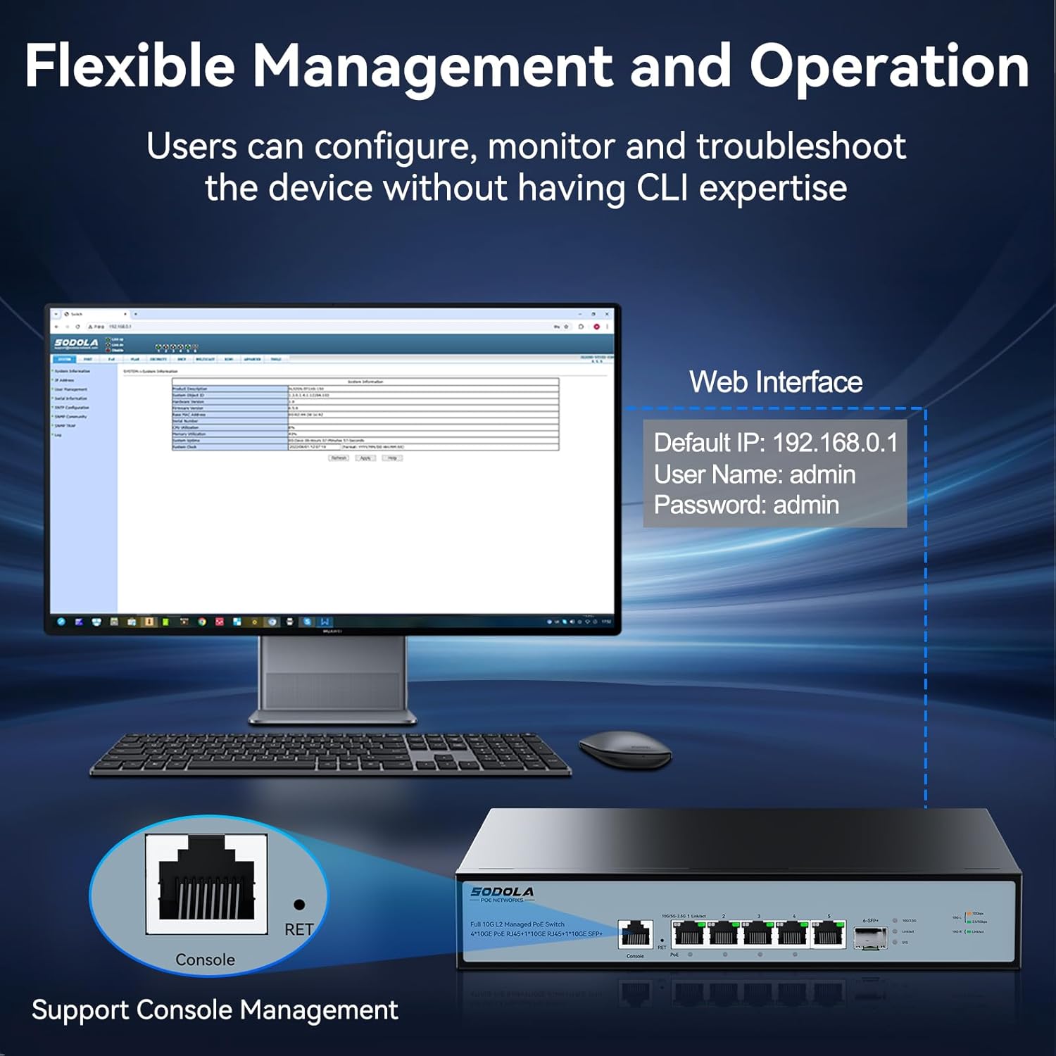
Image 3.3: Accessing the web management interface and console port for configuration.
4. Operating Instructions
4.1. Power over Ethernet (PoE) Functionality
The switch provides Power over Ethernet capabilities to compatible devices.
- Port 1: Supports IEEE802.3af/at/bt standards with a maximum output of 90W.
- Ports 2-4: Support IEEE802.3af/at standards, offering up to 30W per port.
- Total PoE Budget: The switch has a total power supply capacity of 150W for all PoE ports.
When a PoE-compatible device is connected, the switch automatically detects its power requirements and supplies the necessary power. The PoE LED indicator for the respective port will illuminate.

Image 4.1: Diagram illustrating PoE+ IEEE802.3af/at/bt support for various devices.
4.2. Layer 2 Management Features
The switch offers a comprehensive suite of Layer 2 management features accessible via the web interface or console port:
- VLAN (Virtual Local Area Network): Segment your network for improved security and performance.
- LACP (Link Aggregation Control Protocol): Combine multiple physical links into a single logical link for increased bandwidth and redundancy.
- SNMP (Simple Network Management Protocol): Monitor network devices and manage network performance.
- DHCP (Dynamic Host Configuration Protocol): Manage IP address assignment.
- Multicast: Efficiently deliver data to multiple recipients simultaneously (e.g., IGMP).
- MAC Address Management: Control access based on MAC addresses.
- RSTP (Rapid Spanning Tree Protocol): Prevent network loops and ensure network redundancy.
- QoS (Quality of Service): Prioritize network traffic for critical applications.
- ACL (Access Control List): Filter network traffic based on defined rules.
Refer to the online documentation or the switch's web interface help section for detailed configuration guides on each feature.

Image 4.2: Visual representation of the advanced Layer 2 management features supported by the switch.
5. Maintenance
5.1. Cooling and Ventilation
The switch is equipped with an upgraded cooling fan that intelligently adjusts its speed based on power consumption and heat. This ensures optimal operating temperature and near-silent operation during idle times.
- Ensure adequate airflow around the switch. Do not block ventilation openings.
- Avoid placing the switch in enclosed spaces or near heat sources.
5.2. Cleaning
To maintain optimal performance, periodically clean the exterior of the switch.
- Disconnect the power cable before cleaning.
- Use a soft, dry cloth to wipe the surface.
- Do not use liquid or aerosol cleaners, as they may damage the device.
5.3. Firmware Updates
Periodically check the manufacturer's website for available firmware updates. Firmware updates can provide new features, performance improvements, and security enhancements. Follow the instructions provided with the firmware update package carefully.
6. Troubleshooting
This section addresses common issues you might encounter with your Sodola 10Gb L2 Managed PoE Switch.
6.1. No Power
- Ensure the power cable is securely connected to both the switch and the electrical outlet.
- Verify the electrical outlet is functional by plugging in another device.
- Check the SYS LED indicator. If it is off, the switch is not receiving power.
6.2. No Network Link
- Ensure Ethernet cables are securely connected to both the switch port and the network device.
- Verify the cable type is appropriate for the connection speed (e.g., Cat6a or higher for 10Gbps).
- Check the Link/Act LED for the specific port. If it is off, there is no active link.
- Test with a different Ethernet cable or port.
6.3. PoE Not Working
- Confirm the connected device is PoE-compatible and adheres to IEEE802.3af/at/bt standards.
- Check the PoE LED indicator for the port. If it is off, power is not being supplied.
- Ensure the total power consumption of all connected PoE devices does not exceed the switch's 150W PoE budget.
- Verify the device is connected to a PoE-enabled port (Ports 1-4).
6.4. Cannot Access Web Interface
- Ensure your computer's IP address is configured to be in the same subnet as the switch (default 192.168.0.1).
- Clear your web browser's cache.
- Verify you are using the correct default IP address (192.168.0.1) and credentials (admin/admin).
- If the IP address has been changed and forgotten, you may need to perform a factory reset using the reset button on the rear panel.
6.5. Factory Reset
To restore the switch to its factory default settings, locate the Reset button on the rear panel. With the switch powered on, use a paperclip or similar pointed object to press and hold the Reset button for approximately 5-10 seconds until the LEDs indicate a reset process has begun. The switch will then restart with default settings.
7. Specifications
| Feature | Specification |
|---|---|
| Model | 4X10G POE+10G RJ45+SFP+(Managed) |
| Brand | Sodola |
| Interface Type | PoE, SFP+ |
| Number of Ports | 6 (4x 10G PoE, 1x 10G RJ45, 1x 10G SFP+) |
| PoE Standard | IEEE802.3af/at/bt |
| Max PoE Output (Port 1) | 90W |
| Max PoE Output (Ports 2-4) | 30W per port |
| Total PoE Budget | 150W |
| Data Transfer Rate | 10 Gigabits Per Second |
| Backplane Bandwidth | 120Gbps |
| Packet Forwarding Rate | 89.28Mpps |
| MAC Address Table Size | 16K |
| Case Material | Metal |
| Color | Black |
| Item Weight | 4.97 pounds |
| Package Dimensions | 16.1 x 10.91 x 3.66 inches |
| Compatible Devices | Camera, Desktop, Laptop, Printer, Router |
8. Warranty and Support
Your Sodola 10Gb L2 Managed PoE Switch is backed by a one-year warranty, ensuring coverage against manufacturing defects and malfunctions under normal use.
Sodola also provides lifetime after-sales service. A dedicated team of technical engineers is available to assist you with any issues or questions you may have regarding the product. For technical support or warranty claims, please contact Sodola customer service through their official channels or visit the Sodola Store on Amazon.


