1. Introduction
This manual provides detailed instructions for the AYWHP Pro Micro development board, featuring the ATmega32U4 microcontroller. This board is designed for various embedded projects, offering a compact form factor and compatibility with the Arduino IDE. Please read this manual thoroughly before using the product to ensure proper operation and to maximize its potential.
2. Product Overview
The AYWHP Pro Micro is a compact microcontroller board based on the ATmega32U4. It operates at 5V/16MHz and includes a built-in USB Type-C interface for direct programming. Its small size makes it suitable for projects where space is limited, such as custom keyboards or wearable electronics.
Key Features:
- ATmega32U4 microcontroller running at 5V/16MHz.
- Integrated USB Type-C port for programming and serial communication.
- 4 x 10-bit Analog-to-Digital Converter (ADC) pins.
- 12 x Digital Input/Output (I/O) pins, including 5 with Pulse Width Modulation (PWM) capability.
- Dedicated hardware serial ports (Rx and Tx).
- Compatible with Arduino IDE for easy programming.

Figure 1: Detailed pinout diagram of the AYWHP Pro Micro board, showing the Type-C port and various pin functions including serial, ground, power, ADC, and digital I/O.
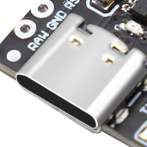
Figure 2: Close-up view of the USB Type-C port on the Pro Micro board, used for power and data transfer.

Figure 3: Close-up view of the ATmega32U4 microcontroller chip, the central processing unit of the Pro Micro board.
3. Specifications
| Feature | Detail |
|---|---|
| Microcontroller | ATmega32U4 |
| Operating Voltage | 5V |
| Clock Speed | 16 MHz |
| Digital I/O Pins | 12 (5 PWM capable) |
| ADC Pins | 4 (10-bit) |
| SRAM | 2.5 KB |
| Flash Memory | 32 KB (4 KB used by bootloader) |
| EEPROM | 1 KB |
| Connectivity | USB Type-C |
| Recommended Power Supply | 6-7V (less than 9V) |
| Dimensions | Approximately 33.45mm x 18.03mm (1.32in x 0.7in) |
| Operating System Compatibility | Windows, macOS, Linux |

Figure 4: Physical dimensions of the AYWHP Pro Micro development board.
4. Setup Instructions
4.1 Power Supply
The Pro Micro board can be powered via the USB Type-C port. For external power, connect a 6-7V DC supply (not exceeding 9V) to the RAW pin. Ensure the power supply is stable and within the recommended voltage range to prevent damage to the board.
4.2 Connecting to a Computer
- Select a Data-Transfer USB-C Cable: It is crucial to use a USB-C cable that supports data transfer, not just charging. Many USB-C cables are designed only for power delivery and will not allow your computer to recognize the Pro Micro.
- Connect the Board: Plug one end of the data-transfer USB-C cable into the Pro Micro's USB port and the other end into your computer.
- Driver Installation: Your operating system should automatically detect the Pro Micro as a Leonardo board. If it is not detected, you may need to manually install the necessary drivers. These drivers are typically included with the Arduino IDE installation.

Figure 5: The Pro Micro board connected to a computer via a USB Type-C cable.
4.3 Arduino IDE Setup
- Download Arduino IDE: If you haven't already, download and install the latest version of the Arduino IDE from the official Arduino website (www.arduino.cc/en/software).
- Board Selection: In the Arduino IDE, go to
Tools > Board > Arduino AVR Boardsand selectArduino Leonardo. The Pro Micro uses the same ATmega32U4 microcontroller as the Leonardo, so this selection is appropriate. - Port Selection: Go to
Tools > Portand select the serial port corresponding to your Pro Micro. It will typically appear as a COM port on Windows or/dev/cu.usbmodemXXXXon macOS/Linux.
5. Operating Instructions
5.1 Programming the Board
Once the Arduino IDE is set up and the board is connected, you can upload your sketches (programs) to the Pro Micro. The process is similar to other Arduino-compatible boards:
- Write Your Sketch: Open a new sketch or load an example in the Arduino IDE.
- Verify Code: Click the 'Verify' button (checkmark icon) to compile your code and check for errors.
- Upload Code: Click the 'Upload' button (right arrow icon) to compile and upload your sketch to the Pro Micro. The board will automatically reset and enter bootloader mode for a few seconds to receive the new program.
5.2 Utilizing I/O Pins
The Pro Micro offers a variety of input/output options for your projects:
- Digital I/O: Use
pinMode(),digitalWrite(), anddigitalRead()functions for digital input and output on pins D0-D12. - Analog Input: Use
analogRead()on pins A0-A3 (which are also D15, D14, D16, D10 respectively) to read analog sensor values. - PWM Output: Pins D3, D5, D6, D9, D10, D11, D13, D14, D16 can be used for PWM output with
analogWrite(). - Serial Communication: The hardware serial ports (Rx and Tx) are available for communication with other devices or for debugging via the Serial Monitor in the Arduino IDE.
- I2C/SPI: The board supports I2C (SDA/SCL on D2/D3) and SPI communication protocols for connecting various sensors and modules.

Figure 6: Examples of the Pro Micro board integrated into different electronic projects, demonstrating its versatility.
6. Maintenance
To ensure the longevity and reliable operation of your AYWHP Pro Micro development board, follow these maintenance guidelines:
- Handle with Care: Avoid dropping the board or subjecting it to physical shock.
- Keep Dry: Protect the board from moisture and liquids, as these can cause short circuits and damage components.
- Cleanliness: Keep the board free from dust and debris. Use a soft, dry brush or compressed air for cleaning. Avoid using liquid cleaners.
- Static Discharge: Always handle the board in an anti-static environment or take precautions to prevent electrostatic discharge (ESD), which can damage sensitive electronic components.
- Proper Storage: When not in use, store the board in an anti-static bag or a protective enclosure.
7. Troubleshooting
7.1 Board Not Detected by Computer
- Check USB Cable: Ensure you are using a USB Type-C cable that supports data transfer, not just charging. Many cables are charge-only and will not allow communication with the board. A good data cable will typically cause LED3 (near pin 7) to blink once when plugged in, and the computer should recognize it as an Arduino Leonardo. If only a solid red LED is present without other activity, the cable might be the issue.
- Install Drivers: If the board is not automatically recognized, ensure the Arduino IDE is properly installed, as it includes the necessary drivers. You might need to manually update or install drivers through your operating system's device manager.
- Try Different USB Port/Computer: Test with a different USB port on your computer or another computer to rule out port or system-specific issues.
- Inspect USB-C Port: Visually inspect the USB-C port on the Pro Micro for any physical damage or bent pins. Some users have reported issues with the durability of the USB-C port.
7.2 Sketch Upload Errors
- Correct Board and Port: Verify that
Arduino Leonardois selected underTools > Boardand the correct COM/serial port is selected underTools > Portin the Arduino IDE. - Timing for Upload: The Pro Micro enters bootloader mode for a short period after reset. If you encounter upload issues, try pressing the reset button (if available, or briefly shorting the RST pin to GND) just before clicking the 'Upload' button in the IDE.
- Code Errors: Ensure your sketch compiles without errors. Check the output window in the Arduino IDE for specific error messages.
7.3 Board Not Responding
- Power Check: Ensure the board is receiving adequate power (5V via USB or 6-7V via RAW pin).
- Short Circuits: Check for any accidental short circuits on the board or in your wiring.
- Component Damage: If the board was subjected to incorrect voltage, reverse polarity, or excessive current, components might be damaged.
8. Warranty and Support
8.1 Warranty Information
Specific warranty details for the AYWHP Pro Micro development board are not provided in the product information. Please refer to the retailer's return policy or contact the seller directly for information regarding warranty coverage.
8.2 Technical Support
For technical assistance, troubleshooting, or further inquiries, please refer to the following resources:
- Online Resources: The Arduino community forums and documentation for the ATmega32U4 microcontroller are excellent resources for programming and project guidance.
- Seller Contact: For product-specific support, contact the seller (Quan Ruiqi) through the Amazon platform or their official support channels if available.
- Product Page: Visit the product page on Amazon for any updated information or frequently asked questions: https://www.amazon.com/dp/B0DFGSHBRL