
1. Introduction
The FUZRR FR3010E is a digital soil resistivity meter and ground resistance tester designed for precise measurement of earth resistance and soil resistivity. This instrument supports two-wire, three-wire, and four-wire test resistance methods, making it suitable for various applications requiring accurate ground system analysis. It features a wide measurement range, high accuracy, and convenient data management functions.
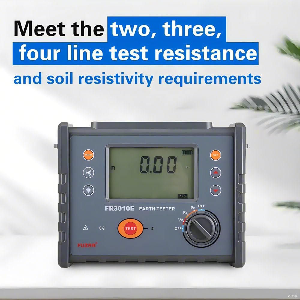
Figure 1: The FR3010E meter, highlighting its versatility for various resistance and resistivity tests.

Figure 2: The FR3010E meter, emphasizing its primary function as a ground resistance and soil resistivity tester with data storage and alarm capabilities.
2. Safety Information
Read all safety warnings and instructions carefully before operating the instrument. Failure to follow these instructions may result in electric shock, fire, or serious injury.
- Always ensure the instrument is in good working condition before use.
- Do not operate the instrument in wet conditions or in the presence of explosive gases or fumes.
- Use only the provided test leads and accessories.
- Ensure proper grounding connections are made before initiating any test.
- Avoid touching exposed wires or terminals during measurements.
- Replace batteries promptly when the low battery indicator appears.
- Do not attempt to repair or modify the instrument. Refer servicing to qualified personnel.
3. Package Contents
Verify that all items listed below are present in your package. If any items are missing or damaged, contact your supplier.

Figure 3: All components included in the FR3010E product package.
- FR3010E Earth Tester (Main Unit)
- Auxiliary Ground Rods (4 PCS)
- Instrument Box
- Standard Test Lines (Red 15m, Yellow 10m, Green 5m)
- Simple Test Lines (Red 1.5m, Green 1.5m)
- Instruction Manual
- Certificate of Guarantee
- Batteries (6 PCS, Lithium-ion)
4. Product Overview
The FR3010E features a clear LCD display and intuitive controls for ease of use.

Figure 4: Front Panel Layout of the FR3010E Earth Tester.
- LCD Display Screen: Shows measurement readings, battery status, and other indicators.
- MEM (Data Retrieval) Button: Accesses stored measurement data.
- Alarm Function Button: Activates or deactivates the alarm for exceeding set values.
- Backlight Function Button: Toggles the display backlight for use in dim conditions.
- SET (Setting) Button: Enters the setting menu.
- Data Scaling Up Button: Used for navigating menus or increasing values.
- Data Reduction Button: Used for navigating menus or decreasing values.
- Test Key: Initiates a measurement.
- Tap Selection Key: Selects different measurement modes or functions.
- Rotary Switch: Selects measurement functions (OFF, PE, RE, VE, OFF+).
5. Setup
5.1 Battery Installation
The FR3010E uses 6 Lithium-ion batteries. Open the battery compartment cover on the back of the instrument, insert the batteries according to the polarity indicators, and then close the cover securely.
5.2 Connecting Test Leads and Auxiliary Rods
Depending on the measurement method (2-pole, 3-pole, or 4-pole), connect the appropriate test leads and auxiliary ground rods to the instrument's terminals (C, P, E, H) and into the ground as per the specific test configuration. Refer to the detailed diagrams in the full instruction manual for correct setup for each measurement type.
6. Operating Instructions
6.1 Power On/Off
Turn the rotary switch to any measurement function (PE, RE, VE) to power on the instrument. To power off, turn the rotary switch to the 'OFF' position. The instrument also features an automatic power-off function (APO) to conserve battery life.
6.2 Measurement Modes
The FR3010E supports precise 3-pole measurement and simple 2-pole measurement for earth resistance, and 4-pole measurement for soil resistivity.
- Earth Resistance (RE): For measuring the resistance of grounding electrodes.
- Earth Voltage (VE): For measuring AC voltage to ground.
- Soil Resistivity (PE): For measuring the resistivity of the soil.
6.3 Performing a Measurement
- Set up the test leads and auxiliary rods according to the desired measurement method.
- Turn the rotary switch to the appropriate measurement function (e.g., RE for earth resistance).
- Press the TEST key to initiate the measurement.
- The measurement result will be displayed on the LCD screen.
- During measurement, the LED flash indicator will be active, and the LCD will count down.
6.4 Data Storage and Retrieval
The instrument can store up to 500 sets of data. After a measurement, press the MEM button to save the reading. To retrieve stored data, press the MEM button repeatedly or use the data scaling buttons to navigate through the records. The display will show 'FULL' if storage is full.
6.5 Backlight Function
Press the backlight button (indicated by a sun icon) to turn the display backlight on or off, improving visibility in low-light conditions.
6.6 Alarm Function
The alarm function can be set to alert the user when a measured value exceeds a predefined threshold. When activated, the instrument will beep to indicate an over-range condition.
7. Maintenance
- Cleaning: Wipe the instrument with a soft, dry cloth. Do not use abrasive cleaners or solvents.
- Battery Replacement: When the battery voltage is low, the instrument will display a low battery indicator and remind you to charge or replace the batteries. Ensure to use the correct type of batteries.
- Storage: Store the instrument in a cool, dry place, away from direct sunlight and extreme temperatures. If storing for an extended period, remove the batteries to prevent leakage.
- Calibration: Regular calibration by qualified personnel is recommended to ensure continued accuracy.
8. Troubleshooting
- No Display/Instrument Not Turning On: Check battery installation and charge level. Replace batteries if necessary.
- "Overflow Display" or "OL" on Screen: This indicates that the measured value exceeds the instrument's range. Check connections, ensure auxiliary rods are properly inserted, or verify the measurement setup.
- Inaccurate Readings: Ensure test leads are securely connected and not damaged. Verify auxiliary rod placement and soil conditions. Calibrate the instrument if readings remain inconsistent.
- Alarm Beeping: This indicates that a measured value has exceeded the set alarm threshold. Check the measurement and adjust settings if needed.
9. Specifications
The following table details the technical specifications of the FUZRR FR3010E Digital Soil Resistivity Meter.

Figure 5: FR3010E Detailed Datasheet.
| Parameter | Specification |
|---|---|
| Model | GT-FR3010 |
| Earthing Resistance Range | 0.01Ω ~ 3000Ω Accuracy ±1.5%rdg ±5dgt |
| Ground Resistance Resolution | 0.01Ω |
| Grounding Voltage Range | 0.01V ~ 600V AC Accuracy ±1.5%rdg ±3dgt |
| Grounding Voltage Resolution | 0.01V |
| Reference Conditions | 23°C ±5°C, 75%RH or less (Auxiliary earth resistance 100Ω ±5%, voltage to ground <10V) |
| Function | Earth ground resistance measurement, voltage to ground measurement, low value resistance measurement |
| Power Supply | DC 6V LR14 battery |
| Backlight | Controllable gray screen backlight, suitable for use in dim places |
| Measuring Mode | Precise 3-pole measurement, simple 2-pole measurement |
| Measuring Method | Earth ground resistance: rated current change-pole method. Test current >20mA (sine wave), 128Hz; Voltage to ground: average value rectification |
| Wire Resistance Verification | Avoid error caused by testing wire that is failed to be fully inserted into tester interface or by poor contact or by users' replacing or lengthening testing wires, making it more accurate for earth ground resistance measurement. |
| Display Mode | 4-digital super-large LCD display, gray screen backlight |
| Measuring Indicator | During measurement, LED flash indicator, LCD count down display |
| LCD Dimension | 108mm × 65mm |
| Dimension | L×W×H: 240mm × 188mm × 85mm |
| Testing Wires | Three wires: each for Red 15m, Yellow 10m, and Green 5m |
| Simple Testing Wire | 2 wires: each for Red 1.5m and Green 1.5m |
| Auxiliary Earthing Rod | 2 PCS |
| Measuring Rate | Voltage to ground: about 2 times/second; earth ground resistance: about 5 seconds/time |
| Measuring Times | Over 5000 times |
| Circuit Voltage | Measuring voltage to ground: measuring below AC 600V |
| Data Storage | 500 sets, flash display "FULL" icon to indicate storage is full |
| Data Read | Data read function: "MR" icon display |
| Overflow Display | Exceeding measuring range overflow function: "OL" icon display |
| Alarm Function | When measuring value exceeds alarm setting value, there is beeper alarming |
| Battery Voltage | Battery power indicate in real time, the battery voltage is low and remind to charge in time |
| Power Consumption | Backlight: 25mA Max Standby: 25mA Max (Backlight shut off) Measurement: 70mA Max (Backlight shut off) |
| Weight | Tester: 1230g (including battery) Testing Wires: 610g (including simply testing wires) Auxiliary earthing rod: 360g (2 PCS) Meter bag: 1200g |
| Working Temperature & Humidity | -10°C ~ 40°C; below 80%RH |
| Storage Temperature & Humidity | -20°C ~ 60°C; below 70%RH |
| Overload Protection | Measuring earth resistance: between each interfaces of E-H, E-S, AC 280V/3 seconds |
| Insulation Resistance | Over 10MΩ (between circuit and enclosure it is 500V) |
| Withstanding Voltage | AC 3700V/rms (Between circuit and enclosure) |
| Electromagnetic Features | IEC61010-4-3, radio frequency electromagnetic field ≤ 1V/m |
| Protection Type | IEC61010-1, IEC61010-2-31, IEC61557-1-5, IEC60529 (IP54), Pollution grade 2, CAT III 300V |
10. Warranty and Support
The FUZRR FR3010E Digital Soil Resistivity Meter comes with a standard manufacturer's warranty. Please refer to the included Certificate of Guarantee for specific terms and conditions. For technical support, service, or warranty claims, please contact your authorized FUZRR dealer or customer service representative.
Keep your purchase receipt and the Certificate of Guarantee as proof of purchase for warranty purposes.