
Introduction
This manual provides detailed instructions for the installation, operation, and maintenance of your Chieftec AZ-01B-OP Mini Tower Computer Case. Please read this manual thoroughly before beginning any installation or operation to ensure proper use and to prevent damage to the product or other components.
The Chieftec AZ-01B-OP is an m-ATX Mini-Tower PC case designed for optimal hardware and cooling compatibility, featuring a brushed front panel and soundproofing material for reduced noise levels.
Safety Information
Observe the following safety precautions during installation and operation:
- Always disconnect the power supply from the wall outlet before installing or removing any components.
- Wear an anti-static wrist strap to prevent electrostatic discharge (ESD) damage to sensitive components.
- Handle components carefully, avoiding contact with pins or circuit boards.
- Ensure all cables are properly routed and secured to prevent interference with cooling fans or moving parts.
- Do not operate the computer case in environments with excessive dust, humidity, or extreme temperatures.
Package Contents
Verify that all items are present in the package:
- Chieftec AZ-01B-OP Mini Tower Computer Case
- Accessory kit (screws, standoffs, cable ties)
- User Manual (this document)
- 1 x 120 mm PWM fan (pre-installed)
Setup and Installation
1. Opening the Case
Remove the side panels to access the interior of the case. Typically, this involves unscrewing thumbscrews at the rear of the case and sliding the panels backward.

Figure 1: Interior view of the Chieftec AZ-01B-OP, showing the main compartment for motherboard and components.
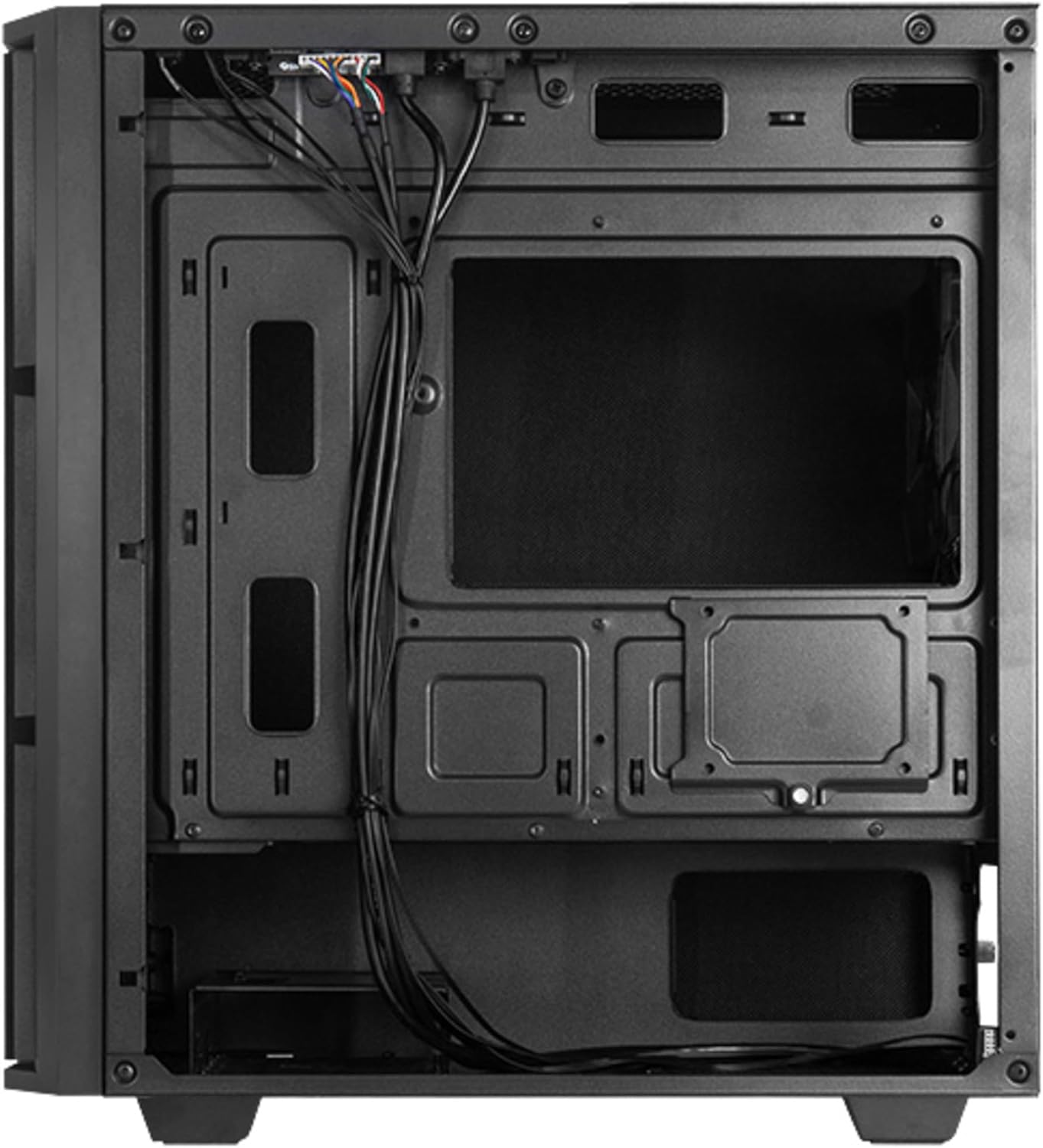
Figure 2: Rear interior view, illustrating cable management space and additional drive mounts.
2. Motherboard Installation
- Install the I/O shield into the rear opening of the case.
- Align the motherboard with the standoffs inside the case. Ensure the standoffs match the motherboard's form factor (Micro ATX).
- Secure the motherboard with the provided screws.
3. Power Supply Installation
- Position the power supply unit (PSU) in the designated bottom-mount area.
- Secure the PSU to the rear of the case with screws.
- Route the necessary power cables through the cable management cutouts.

Figure 3: Rear view of the case, indicating the PSU mounting location.
4. Storage Drive Installation (HDD/SSD)
The case supports multiple drive configurations. Refer to the internal layout for specific mounting points.
- For 3.5" HDDs: Mount drives in the drive cage, typically located at the bottom front or behind the motherboard tray.
- For 2.5" SSDs: Mount drives on dedicated SSD trays or directly onto the motherboard tray using screws.

Figure 4: Bottom view, showing potential HDD/SSD mounting areas and the PSU dust filter.
5. Expansion Card Installation
- Remove the necessary expansion slot covers from the rear of the case.
- Insert the expansion card (e.g., graphics card) into the appropriate PCIe slot on the motherboard.
- Secure the card with a screw or the case's retention mechanism.
6. Cable Management
Utilize the cable routing cutouts and tie-down points behind the motherboard tray to organize cables. This improves airflow and aesthetics.
7. Closing the Case
Once all components are installed and cables are managed, reattach the side panels. Ensure they are properly aligned and secured with the thumbscrews.

Figure 5: Front view of the assembled case.
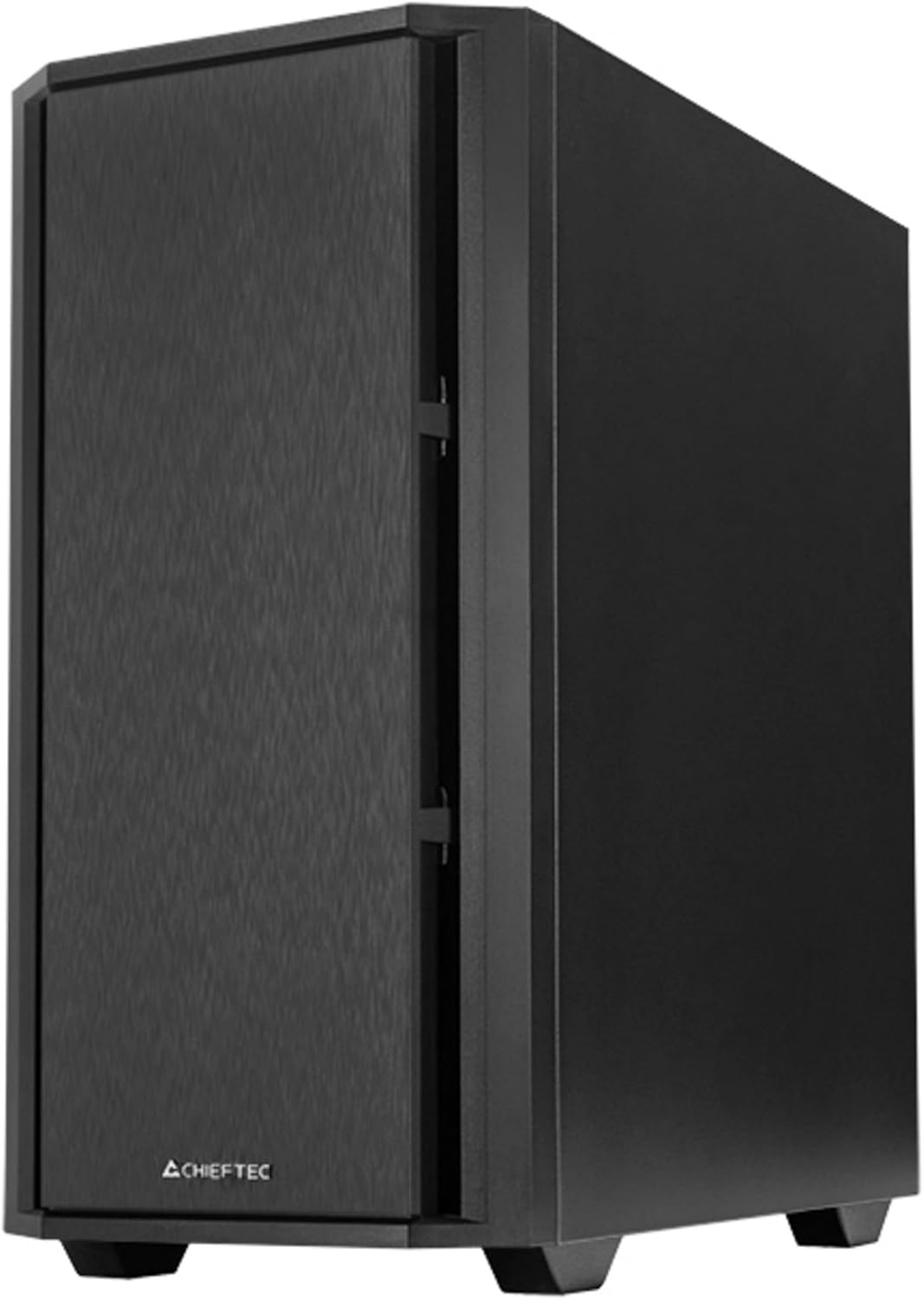
Figure 6: Angled front view of the assembled case.
Operating
1. Connecting Peripherals
Connect your monitor, keyboard, mouse, and other peripherals to the appropriate ports on your motherboard's I/O panel and any installed expansion cards.

Figure 7: Top I/O panel for easy access to USB and audio ports.
2. First Power-On
- Connect the power cable to the PSU and a wall outlet.
- Flip the power switch on the PSU to the 'ON' position.
- Press the power button on the front of the case to start your computer.
Maintenance
1. Cleaning the Case
Regularly clean the exterior of the case with a soft, damp cloth. Avoid abrasive cleaners or solvents.
2. Dust Filter Maintenance
The Chieftec AZ-01B-OP includes dust filters to prevent dust buildup inside the system. Periodically remove and clean these filters (e.g., with compressed air or by washing with water and allowing to dry completely) to maintain optimal airflow and cooling performance.
Troubleshooting
If you encounter issues, consider the following common solutions:
- No Power: Ensure the power cable is securely connected to both the PSU and the wall outlet. Check that the PSU switch is in the 'ON' position. Verify all internal power cables (24-pin ATX, 8-pin CPU, GPU power) are correctly seated.
- No Display: Confirm the monitor is connected to the graphics card (not the motherboard's integrated graphics ports, unless you are using integrated graphics). Reseat the graphics card and RAM modules.
- Overheating: Check that all case fans and CPU cooler fans are spinning. Ensure dust filters are clean and not obstructing airflow. Verify proper thermal paste application on the CPU.
- Unusual Noise: Identify the source of the noise. It could be a loose cable hitting a fan, a faulty fan, or a hard drive. Secure loose components or replace faulty fans.
Specifications
| Feature | Specification |
|---|---|
| Brand | Chieftec |
| Model Name | AZ-01B-OP |
| Case Type | Mini-Tower |
| Motherboard Compatibility | Micro ATX |
| Material | Alloy Steel |
| Color | Black |
| Item Weight | 5.15 Kilograms (11.33 pounds) |
| Product Dimensions (LxWxH) | 18.9 x 18.9 x 10.63 inches |
| Power Supply Mounting Type | Bottom Mount |
| Cooling Method | Air |
| Pre-installed Fans | 1 x 120 mm PWM fan |
| Special Features | Sound-absorbing material, Elegant and modern design |
Warranty Information
Chieftec products are manufactured to high-quality standards. This product is covered by a limited warranty against defects in materials and workmanship. The specific warranty period and terms may vary by region and retailer. Please retain your proof of purchase for warranty claims.
For detailed warranty information, please refer to the official Chieftec website or contact your local retailer.
Support
For technical assistance, troubleshooting, or further inquiries, please visit the official Chieftec support website or contact their customer service department.
- Official Website: www.chieftec.eu
- Support Contact: Refer to the website for regional contact information.


