1. Product Overview
The eletechsup R413E16 is a versatile 16-channel multifunction RS485 control core board designed for various industrial and home automation applications. It supports both AT commands and Modbus RTU commands, allowing flexible control over relay modules. This core board facilitates communication via RS485 and RS232 (TTL) interfaces, providing 16 output control pins with 5V TTL level.
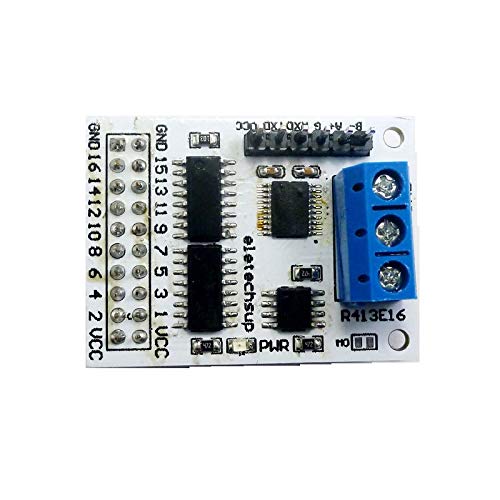
Figure 1: eletechsup R413E16 16-Channel RS485 Relay Control Core Board (A version shown).
Note: A separate relay board is required for relay functionality and must be purchased independently or prepared by the user. The R413E16 acts as the control core.
2. Specifications
| Feature | Description |
|---|---|
| Operating Voltage | DC 5V |
| Operating Current | 11-15mA |
| Control Commands | 'open', 'close', 'Momentary', 'Self-locking', 'Interlock', 'Delay' (6 commands) |
| Instruction Control Modes | AT command, MODBUS command (automatic recognition) |
| AT Command Max Delay | 9999 seconds |
| MODBUS Command Max Delay | 255 seconds |
| MODBUS Slave ID Support | Up to 247 devices in parallel |
| Bus Interfaces | RS485, RS232 (TTL) |
| Output Control Pins | 16 pins, 5V TTL level |
| Output Level | Low level (default) / High level (selectable via M0 jumper) |
| Dimensions (A version) | 40 x 30 x 22mm |
| Dimensions (B version) | 40 x 30 x 11.5mm |
| Weight (A version) | 9.2g |
| Weight (B version) | 6.2g |
| Model Number | R413E16 |
3. Version Identification
The R413E16 core board is available in two versions, A and B, designed for different integration needs:
- A Version: Features solder pins on top and screw terminals, making it suitable for easy insertion into existing relay boards. The output control port is a 2.54mm female header.
- B Version: Features solder pins on the bottom and no screw terminals, designed for easy embedding into custom PCBs. The output control port is a 2.54mm male header.
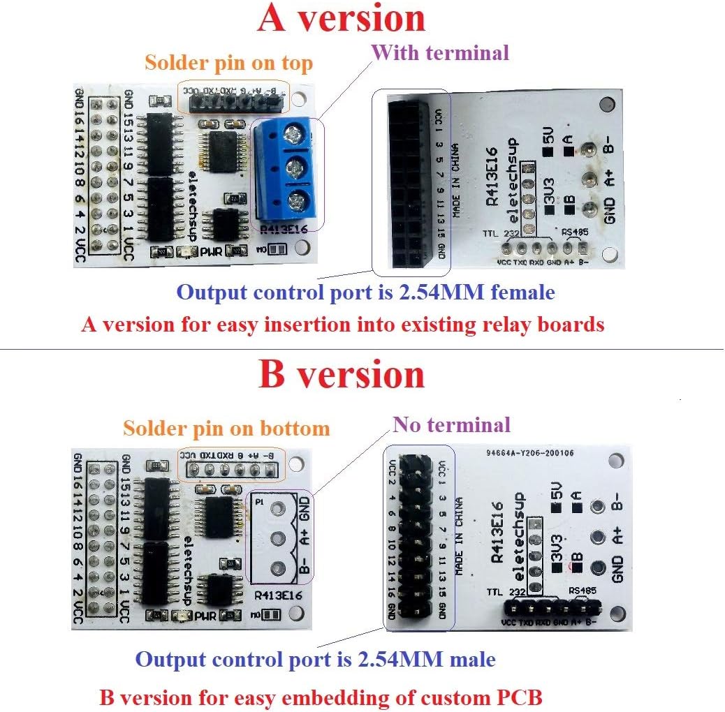
Figure 2: Comparison between A version (top) and B version (bottom) of the R413E16 core board, highlighting terminal and pin differences.
4. Setup and Connections
Proper connection of the R413E16 core board is crucial for its functionality. Ensure all power and communication lines are correctly wired before operation.
4.1 Pinout and Interfaces
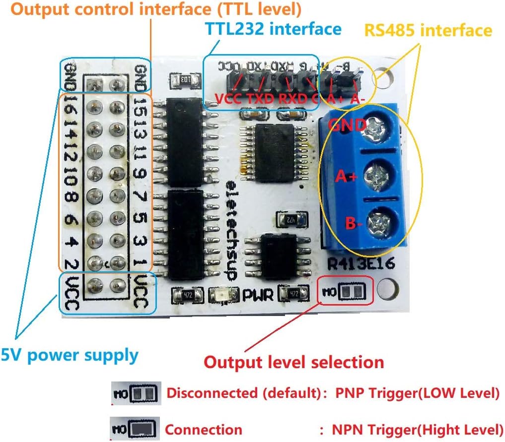
Figure 3: Detailed pinout and interface diagram for the R413E16 core board, showing 5V power supply, output control interface (TTL level), TTL232 interface, RS485 interface, and output level selection jumper (M0).
- 5V Power Supply: Connect DC 5V to the VCC and GND pins.
- Output Control Interface (TTL Level): 16 pins (GND, 16, 14, 12, 10, 8, 6, 4, 2, VCC, 15, 13, 11, 9, 7, 5, 3, 1) provide 5V TTL level outputs for controlling external devices like relay boards.
- RS485 Interface: Connect A+ and B- for RS485 communication.
- RS232 (TTL) Interface: Connect VCC, TXD, RXD, GND for TTL serial communication. For optimal TTL operation, it is recommended to remove the SP485 chip if not using RS485.
4.2 Output Level Selection
The output level of the control pins can be configured using the M0 jumper:
- M0 Disconnected (Default): Configures the output for Low level output (PNP Trigger).
- M0 Connected: Configures the output for High level output (NPN Trigger).
4.3 Connecting to a Relay Module
The R413E16 core board is designed to control 1-16 channel relay modules (5V/6V/9V/12V/24V). Ensure the relay module's voltage matches the control board's output capabilities or is appropriately interfaced.
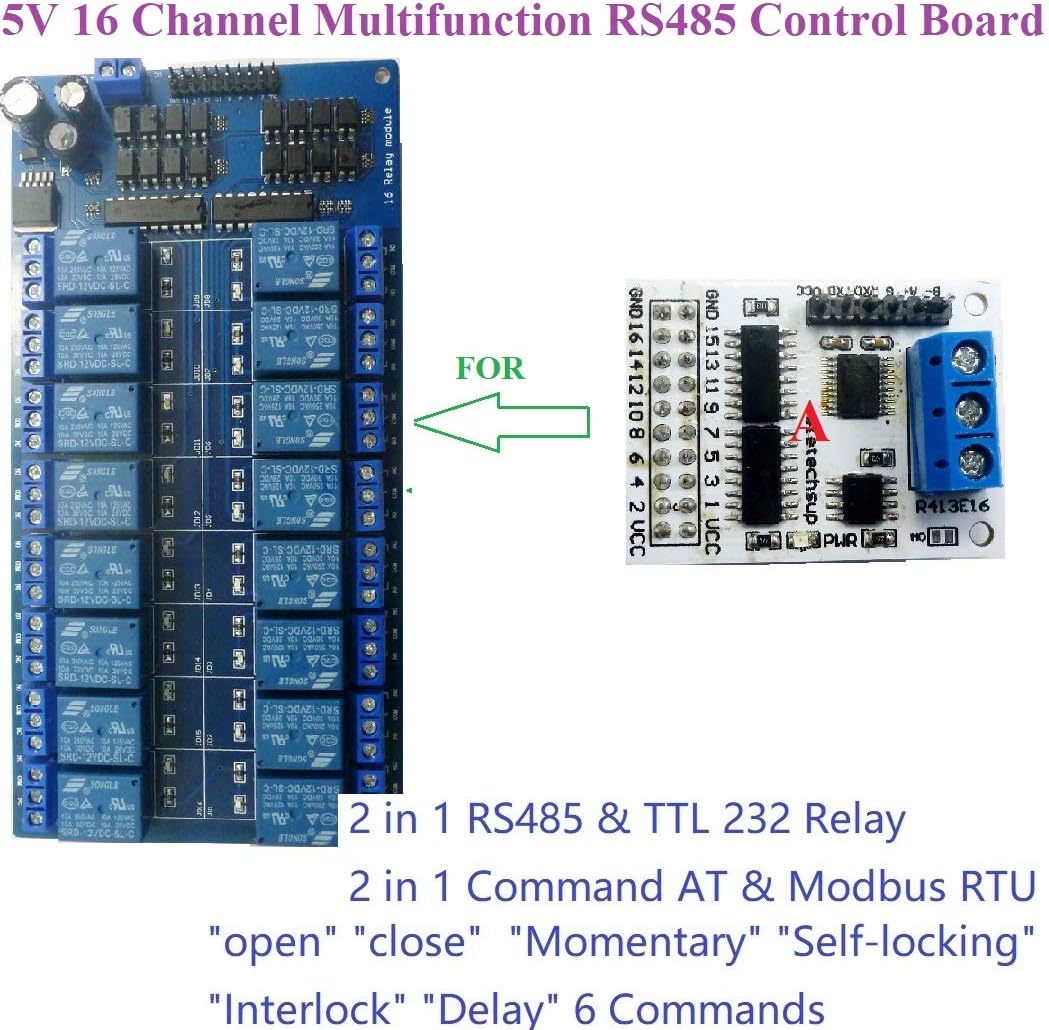
Figure 4: The R413E16 core board connected to a 16-channel relay module, demonstrating its integration for controlling multiple relays.
5. Operating Instructions
The R413E16 supports two primary instruction control modes: AT command mode and MODBUS command mode. The board automatically recognizes which command type is being sent, eliminating the need for manual switching.
5.1 AT Command Mode
In AT command mode, you can control the relay board using simple AT commands sent via a serial HyperTerminal (serial assistant) on a PC. This mode supports a maximum delay of 9999 seconds for timed operations.

Figure 5: A PC connected to the R413E16 core board via a USB-to-RS485 converter for sending AT or MODBUS commands.
5.2 MODBUS Command Mode
MODBUS command mode offers more advanced control options and is suitable for integration into larger systems. It supports a maximum delay of 255 seconds.
- Control Methods: MODBUS commands can be sent via serial HyperTerminal (requires manual CRC calculation), Modbus Poll software (automatically adds CRC), or through a PLC/MCU.
- Slave ID: In MODBUS command mode, the R413E16 can operate as a slave device. You can set different Slave IDs (up to 247) by command, allowing multiple modules to be connected in parallel on the same RS485 bus. The correct Slave ID must be used for communication.

Figure 6: Example setup showing a PC controlling multiple R413E16 modules (Slave ID 1, 2, 3, up to 247) using MODBUS commands over RS485.
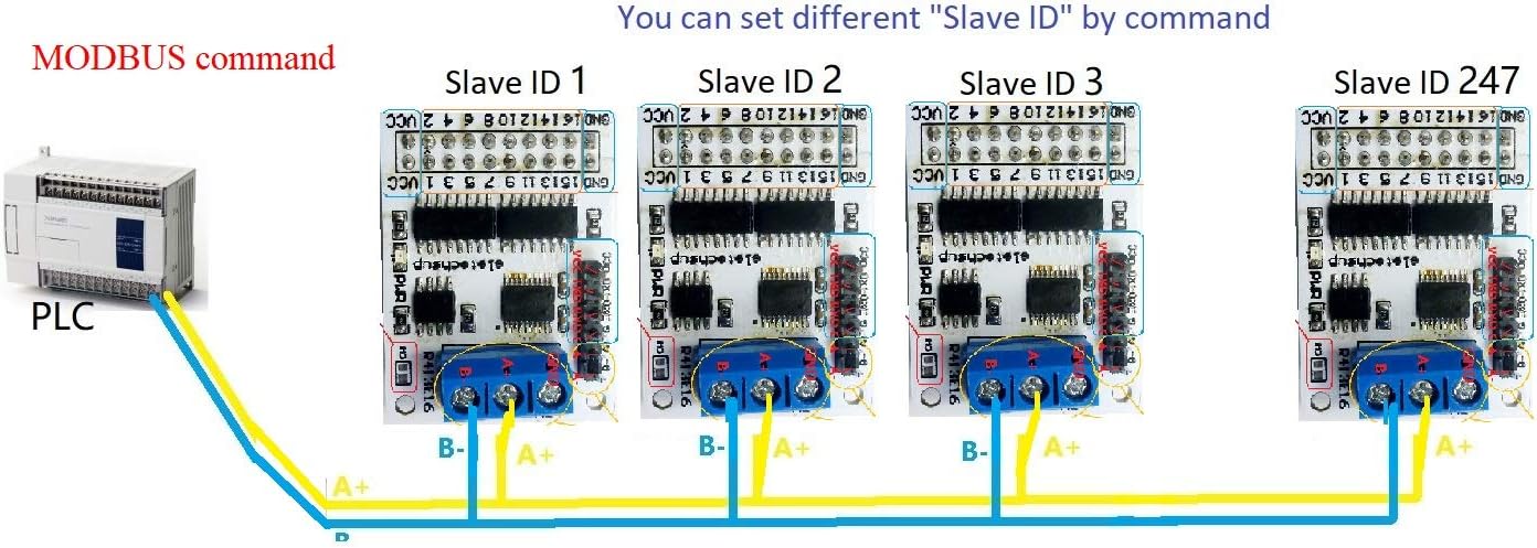
Figure 7: Example setup showing a PLC controlling multiple R413E16 modules (Slave ID 1, 2, 3, up to 247) using MODBUS commands over RS485.
For detailed command descriptions and protocols, please refer to the '16 Channel Multifunction RS485 Module Command' document, which can be obtained from the manufacturer after purchase.
6. Applications
The R413E16 core board is suitable for a wide range of applications, including but not limited to:
- Automated industrial PLC systems
- Smart Home and Home Automation projects
- Identification systems
- Motor Forward & Backward control
- CCTV Camera PTZ (Pan-Tilt-Zoom) control
- Security systems
- LED dot matrix screen control
- RS485 remote control applications
- DIY electronic projects
7. Troubleshooting
If you encounter issues with your R413E16 module, consider the following common troubleshooting steps:
- No Power: Verify that the DC 5V power supply is correctly connected and providing stable voltage. Check for loose connections.
- Communication Failure:
- Ensure RS485 A+ and B- lines are not reversed.
- Check serial port settings (baud rate, data bits, stop bits, parity) match the module's configuration.
- In MODBUS mode, confirm the Slave ID is correctly set and matches the command.
- If using TTL, ensure the SP485 chip is removed if necessary for direct TTL communication.
- Relay Not Actuating:
- Confirm the relay board is correctly connected to the R413E16's output pins.
- Verify the relay board has its own power supply if required.
- Check the M0 jumper setting for output level (PNP/NPN) matches the relay board's trigger requirements.
- Ensure the correct command is being sent for the desired relay action ('open', 'close', etc.).
- Incorrect Delay: Double-check the delay value in your AT or MODBUS command. Remember the maximum delays are 9999 seconds for AT and 255 seconds for MODBUS.
If problems persist, consult the detailed command documentation or contact eletechsup customer support.
8. Maintenance
The R413E16 core board is designed for reliable operation with minimal maintenance. Follow these guidelines to ensure longevity:
- Environment: Operate the module within its specified temperature and humidity ranges. Avoid exposure to excessive dust, moisture, or corrosive substances.
- Cleaning: If cleaning is necessary, gently wipe the board with a dry, soft cloth. Do not use liquid cleaners or solvents.
- Connections: Periodically inspect all connections for tightness and corrosion, especially in industrial environments.
- Power Supply: Ensure a stable and clean power supply (DC 5V) to prevent damage to the module.
9. Warranty and Support
For warranty information, technical support, or to obtain the detailed '16 Channel Multifunction RS485 Module Command' document, please contact eletechsup directly through their official channels or the platform where the product was purchased. Keep your purchase receipt for warranty claims.
Manufacturer: eletechsup
Model Number: R413E16
Date First Available: August 22, 2024