1. Introduction
The Treedix Coaxial and RJ45 Network Cable Tester (Model TRX5-0757R) is a versatile diagnostic tool designed for efficient testing of various cable types. This device supports both Coaxial (BNC or F-style) and RJ45 connectors, including shielded and unshielded network cables. It is engineered to detect common wiring faults such as short circuits, open circuits, and cross-wiring, ensuring reliable network operation and maintenance. Its portable, split design allows for both local and remote testing, making it suitable for a wide range of applications from routine checks to broadband installations and circuit repairs.

Image 1.1: The Treedix Network Cable Tester, highlighting its capability to measure shield lines with a high-sensitivity chip. The tester is shown next to network equipment.
2. Components Included
The package for the Treedix Coaxial and RJ45 Network Cable Tester includes the following items:
- Main Tester Unit
- Remote Tester Unit
- Instruction Manual (this document)
Note: A 9V DC battery is required for operation and is not included in the package. Please ensure you have a 9V battery available before attempting to use the tester.
3. Setup
3.1 Battery Installation
The Treedix Network Cable Tester requires one 9V DC battery for power. Follow these steps to install the battery:
- Locate the battery compartment on the back of the main tester unit.
- Gently slide open the battery compartment cover.
- Connect a 9V battery to the battery clip inside the compartment, ensuring correct polarity.
- Place the battery into the compartment.
- Close the battery compartment cover securely.

Image 3.1: The main tester unit with its battery compartment open, illustrating where to connect and insert a 9V battery.
3.2 Identifying Tester Components
Familiarize yourself with the key components and indicators of the tester:

Image 3.2: A detailed diagram labeling the BNC connectors, RJ45 connector sockets, RJ45 test indicators (PIN NO. 1-8, GND), BNC display light, and the power button with its modes (3S-ON, 1S-A/M, 5S-OFF).
- BNC Connector: For connecting coaxial cables.
- RJ45 Connector Socket: For connecting RJ45 Ethernet cables.
- RJ45 Test Indicator (PIN NO. 1-8, GND): LEDs that illuminate to show the continuity and wiring status of each pin in an RJ45 cable.
- BNC Display Light: An LED indicator for coaxial cable testing.
- Power Button: Controls the device's power and test modes.
- 3S-ON: Press and hold for 3 seconds to power on.
- 1S-A/M: Press for 1 second to switch between Auto and Manual test modes.
- 5S-OFF: Press and hold for 5 seconds to power off.
4. Operation
The Treedix Network Cable Tester can be used for both local and remote testing of RJ45 and Coaxial cables.
4.1 Powering On and Off
- To power on the tester, press and hold the power button for approximately 3 seconds until the power indicator light illuminates.
- To power off the tester, press and hold the power button for approximately 5 seconds until the power indicator light turns off.
4.2 RJ45 Cable Testing (Network Cables)
This tester supports testing of both shielded and unshielded RJ45 network cables (e.g., Cat5, Cat5e, Cat6).
- Ensure the tester is powered on.
- Connect one end of the RJ45 cable to the RJ45 port on the Main Tester Unit.
- Connect the other end of the RJ45 cable to the RJ45 port on the Remote Tester Unit. For local testing of short cables, the remote unit can be attached directly to the main unit.
- Observe the LED indicators (PIN NO. 1-8, GND) on both the main and remote units.
- Normal Connection: All 8 lights (1-8) and the GND light on both units will illuminate in sequence, indicating a correct straight-through connection.
- Fault Detection:
- Open Circuit: If a specific pin's LED does not light up on either the main or remote unit, it indicates an open circuit for that wire.
- Short Circuit: If two or more pins' LEDs light up simultaneously or in an incorrect sequence, it indicates a short circuit between those wires.
- Cross-Wiring/Miswire: If the sequence of lights is incorrect (e.g., pin 1 on main lights up with pin 2 on remote), it indicates a cross-wire or miswire.
- Shielded Cable Test: The GND light will indicate the status of the shield.

Image 4.1: Illustration of RJ45 test results. A "Connected" state shows all 1-8 lights on, while a "Poor connection" indicates specific lights are off, signifying a fault.

Image 4.2: A close-up view of the main tester unit, clearly showing the BNC and RJ45 ports for cable connections.
4.3 Coaxial Cable Testing (BNC/F-Style)
The tester can identify signal issues in coaxial cables with BNC or F-style connectors (using appropriate adapters, not included).
- Ensure the tester is powered on.
- Connect one end of the coaxial cable to the BNC connector on the Main Tester Unit.
- Connect the other end of the coaxial cable to the BNC connector on the Remote Tester Unit.
- Observe the BNC display light.
- Normal Connection: The BNC display light will illuminate steadily, indicating continuity.
- Fault Detection: If the BNC display light does not illuminate or flashes intermittently, it indicates a fault such as an open circuit or poor connection in the coaxial cable.
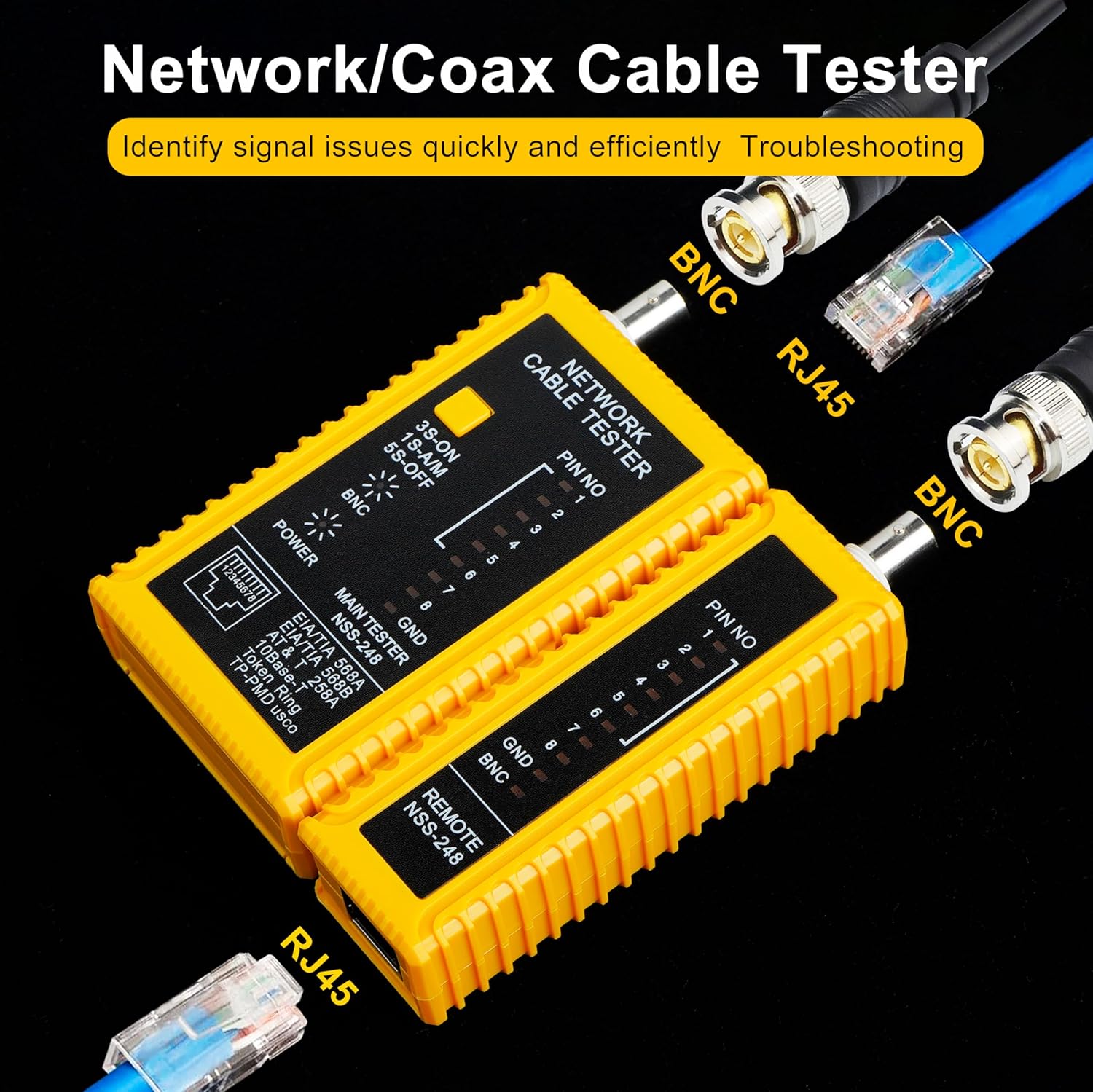
Image 4.3: The Treedix tester demonstrating connections for both RJ45 and BNC cables, illustrating its dual testing capability.
4.4 Local and Remote Testing
The tester's split design allows for flexible testing scenarios:
- Local Testing: For shorter cables or when both ends are accessible, the remote unit can be detached and connected to the other end of the cable, or for very short cables, it can remain attached to the main unit.
- Remote Testing: For installed cables or cables running through walls, the remote unit can be taken to the distant end of the cable while the main unit remains at the starting point. This enables one person to perform comprehensive cable testing.

Image 4.4: The main and remote units of the Treedix tester separated, demonstrating its capability for both local and remote cable testing.
5. Maintenance
Proper maintenance ensures the longevity and accuracy of your Treedix Network Cable Tester.
- Cleaning: Use a soft, dry cloth to clean the exterior of the tester. Do not use abrasive cleaners or solvents.
- Storage: Store the tester in a cool, dry place away from direct sunlight and extreme temperatures.
- Battery Replacement: If the power indicator light dims or the tester does not function correctly, replace the 9V battery. Remove the battery if the tester will not be used for an extended period to prevent leakage.
- Handling: Avoid dropping the tester or subjecting it to strong impacts, as this can damage internal components.
6. Troubleshooting
If you encounter issues with your Treedix Network Cable Tester, refer to the following common problems and solutions:
| Problem | Possible Cause | Solution |
|---|---|---|
| Tester does not power on. | Dead or improperly installed 9V battery. | Check battery installation and replace with a fresh 9V battery if necessary. Ensure correct polarity. |
| RJ45 LEDs do not light up or show incorrect sequence. | Cable fault (open, short, cross-wire, miswire) or poor connection. |
|
| BNC display light does not illuminate or flashes. | Coaxial cable fault (open circuit, poor connection) or damaged BNC connector. |
|
| Tester units do not separate or re-attach smoothly. | Obstruction or misalignment. | Ensure no debris is present in the sliding mechanism. Align the units carefully before attempting to slide them together or apart. Do not force. |
7. Specifications
| Feature | Detail |
|---|---|
| Brand | Treedix |
| Model Number | TRX5-0757R |
| Supported Cable Types | Coaxial (BNC, F-style with adapter), RJ45 Ethernet (shielded/unshielded) |
| Fault Detection | Open circuit, short circuit, cross-wiring, miswire |
| Power Source | 1x 9V DC Battery (not included) |
| Measurement Type | Ohmmeter (for continuity) |
| Item Weight | 105 Grams (approx. 3.7 ounces) |
| Dimensions (Package) | Approximately 5 x 5 x 1.1 inches |
| Color | Yellow |
8. Warranty Information
Treedix products are manufactured to high-quality standards. For specific warranty details, including coverage period and terms, please refer to the product packaging or contact Treedix customer support. Keep your purchase receipt as proof of purchase for any warranty claims.
9. Customer Support
If you have any questions, require technical assistance, or need to report an issue with your Treedix Network Cable Tester, please contact our customer support team. You can typically find contact information on the Treedix official website or through the retailer where you purchased the product.
For additional resources and product information, visit the Treedix Store on Amazon.


