1. Introduction
The waveshare ESP32-S3 4.3inch Capacitive Touch LCD Development Board Type B with Case is a microcontroller development board featuring 2.4GHz WiFi and BLE 5 support. It integrates high-capacity Flash and PSRAM, and an onboard 4.3-inch capacitive touch screen capable of running GUI programs like LVGL. This board is designed for rapid development of Human-Machine Interface (HMI) applications and other ESP32-S3 based projects.
Key features include:
- Xtensa 32-bit LX7 dual-core processor, operating up to 240MHz.
- Integrated 2.4GHz Wi-Fi (802.11 b/g/n) and Bluetooth 5 (LE) with an onboard antenna.
- Built-in 512KB SRAM and 384KB ROM, with onboard 16MB Flash and 8MB PSRAM.
- 4.3-inch capacitive touch display with 800×480 resolution and 65K colors.
- 5-point capacitive touch control via I2C interface, with interrupt support.
- Onboard voltage regulator supporting 7-36V wide range power supply.
- RTC chip and rechargeable battery for time data retention during power loss.
- CAN, RS485, I2C interfaces, TF card slot, GH1.25 2P battery header, and digital isolated IO interfaces.
- Supports passive and active digital input with bi-directional optocoupler isolation.
- Digital output with optocoupler isolation, providing up to 450mA sinking current.
- LED indicators for power and battery charging status.
- Flexible clock and module power supply settings for low power consumption.
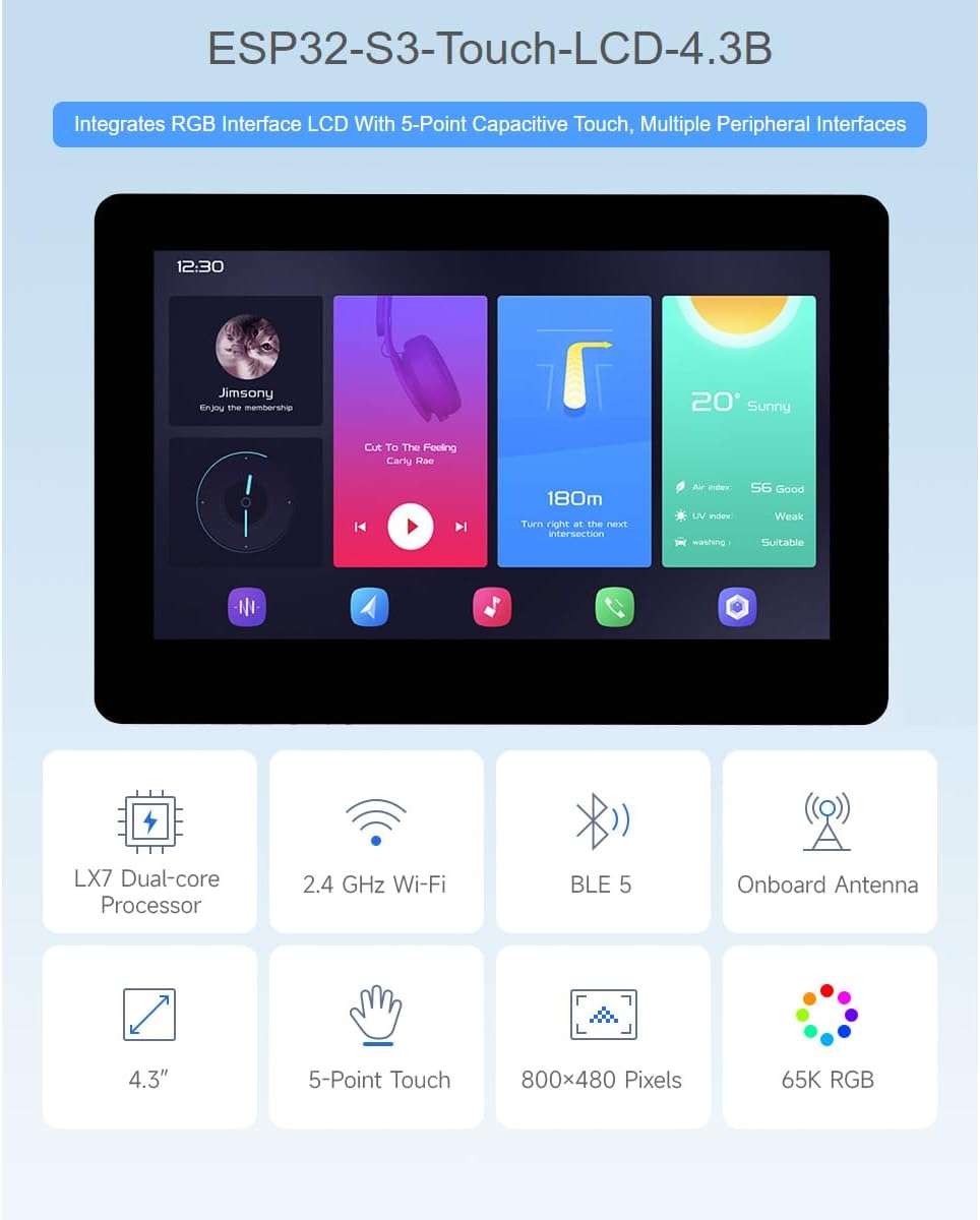
Figure 1: Overview of the ESP32-S3 4.3inch Touch LCD Development Board's main features, including LX7 Dual-core Processor, 2.4 GHz Wi-Fi, BLE 5, Onboard Antenna, 4.3-inch display, 5-Point Touch, 800x480 Pixels, and 65K RGB color depth.
2. Package Contents
The standard package includes the following items:
- ESP32-S3-Touch-LCD-4.3B-BOX x1

Figure 2: The ESP32-S3 4.3inch Touch LCD Development Board Type B, enclosed in its protective case.
3. Hardware Overview
This section details the various components and interfaces available on the ESP32-S3 4.3inch Touch LCD Development Board.
3.1 Onboard Components
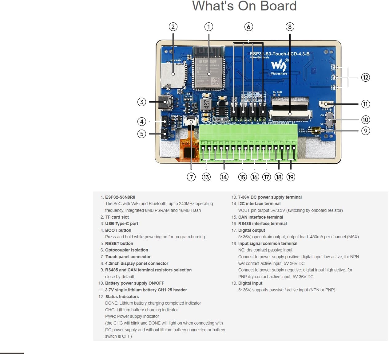
Figure 3: Labeled diagram of the ESP32-S3 4.3inch Touch LCD Development Board's components.
- ESP32-S3N8R8: The System-on-Chip (SoC) with Wi-Fi and Bluetooth, operating up to 240MHz, integrated 8MB PSRAM and 16MB Flash.
- TF card slot: For external storage.
- USB Type-C port: For power supply and data communication.
- BOOT button: Press and hold while powering on for program burning.
- RESET button: Resets the board.
- Optocoupler Isolation: Provides electrical isolation for certain I/O.
- Touch panel connector: Connects to the capacitive touch screen.
- 4.3inch display panel connector: Connects to the LCD display.
- RS485 and CAN terminal resistors selection: Jumpers to enable/disable terminal resistors (close by default).
- Battery power supply ON/OFF: Switch for controlling battery power.
- 3.7V single lithium battery GH1.25 header: Connector for a rechargeable lithium battery.
- Status Indicators:
- DONE: Lithium battery charging completed indicator.
- CHG: Lithium battery charging indicator.
- PWR: Power supply indicator.
- Note: The CHG will blink and DONE will light when connecting with DC power supply and without lithium battery connected or battery switch is OFF.
- 7-36V DC power supply terminal: Main power input.
- I2C interface terminal: VOUT pin output 5V/3.3V (switchable on board resistor).
- CAN interface terminal: For CAN bus communication.
- RS485 interface terminal: For RS485 communication.
- Digital output: 5-36V, open-drain output, output load: 450mA per channel (MAX).
- Input signal common terminal:
- NC: Dry contact/passive input.
- Connect to power supply positive: digital input low active, for NPN wet contact active input, 5V-36V DC.
- Connect to power supply negative: digital input high active, for PNP dry contact active input, 5V-36V DC.
- Digital input: 5-36V, supports passive / active input (NPN or PNP).
3.2 Peripheral Interfaces
The board supports expansion with various peripherals through dedicated interfaces.
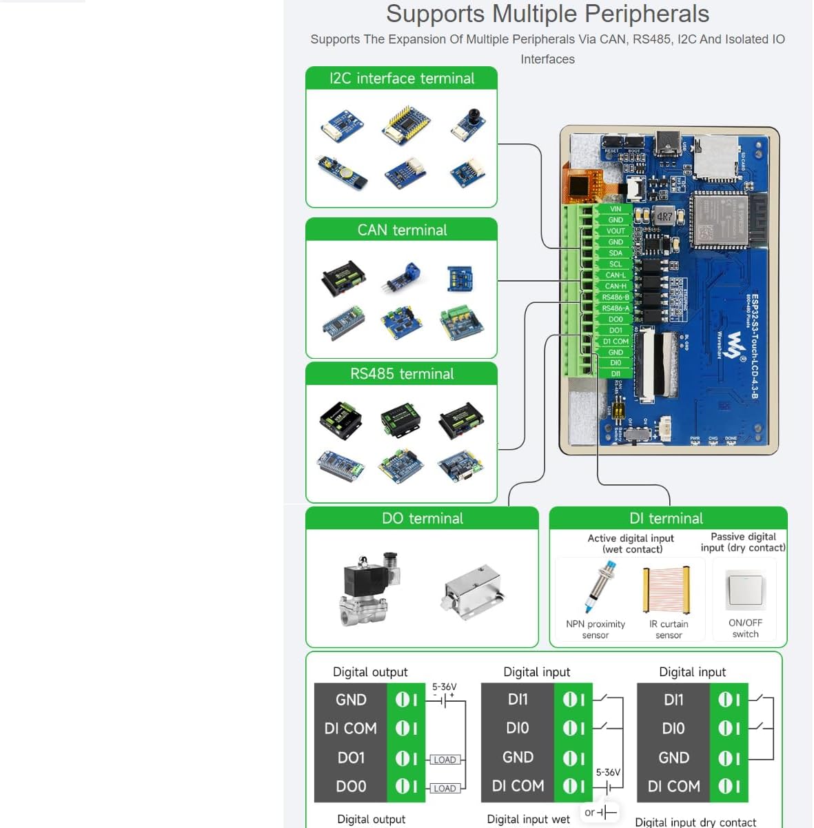
Figure 4: Illustration of the board's peripheral expansion capabilities, including I2C, CAN, RS485, Digital Output (DO), and Digital Input (DI) terminals.
- I2C Interface: For connecting I2C compatible sensors and modules.
- CAN Terminal: Enables communication over a CAN bus network.
- RS485 Terminal: Facilitates long-distance serial communication.
- DO Terminal (Digital Output): Optocoupler isolated outputs for controlling external devices with higher driving capability.
- DI Terminal (Digital Input): Optocoupler isolated inputs supporting both active (wet contact) and passive (dry contact) signals.
4. Setup Instructions
Follow these steps to set up your ESP32-S3 development board.
4.1 Power Supply
- Connect a 7-36V DC power supply to the designated terminal (13 in Figure 3).
- Alternatively, power the board via the USB Type-C port (3 in Figure 3).
- For portable applications, connect a 3.7V single lithium battery to the GH1.25 header (11 in Figure 3) and ensure the battery power switch (10 in Figure 3) is ON.
4.2 Wiring Methods
The board supports two primary wiring methods for integration into various systems.
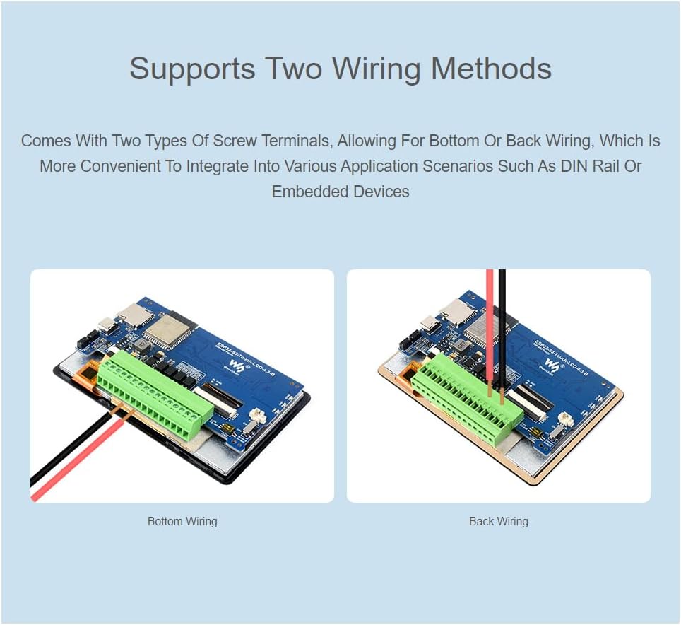
Figure 5: Comparison of bottom wiring and back wiring methods for connecting to the board's terminals.
- Bottom Wiring: Wires are connected from the bottom of the terminal blocks, suitable for flush mounting or integration where space above the terminals is limited.
- Back Wiring: Wires are connected from the back of the terminal blocks, often preferred for DIN rail mounting or embedded devices where access from the rear is convenient.
4.3 Initial Programming
To upload firmware to the ESP32-S3, connect the board to your computer via the USB Type-C port. Press and hold the BOOT button (4 in Figure 3) while powering on or resetting the board to enter programming mode. Release the BOOT button after the board starts up. Use development environments such as the Arduino IDE or ESP-IDF to compile and upload your code.
5. Operating Instructions
Once programmed, the ESP32-S3 board operates according to the uploaded firmware. The integrated display and touch functionality are key aspects of its operation.
5.1 Capacitive Touch Display
The 4.3-inch capacitive touch screen supports 5-point multi-touch input, enabling intuitive user interaction for HMI applications.

Figure 6: A hand interacting with the capacitive touch screen, illustrating its multi-point touch capability.
- The touch functionality is managed via an I2C interface, allowing for precise and responsive input.
- Develop graphical user interfaces using libraries like LVGL to leverage the full potential of the display.
5.2 Wireless Connectivity
The ESP32-S3 features integrated 2.4GHz Wi-Fi and Bluetooth 5 (LE) for wireless communication.
- Wi-Fi: Connect to local networks for internet access, data transfer, or IoT applications.
- Bluetooth 5 (LE): Establish low-energy connections with other Bluetooth-enabled devices for data exchange or control.
6. Application Scenarios
The versatility of the ESP32-S3 4.3inch Touch LCD Development Board makes it suitable for a wide range of applications.

Figure 7: Examples of how the ESP32-S3 board can be utilized in Human-machine Interface and LVGL GUI development.
- Human-Machine Interface (HMI): Develop intuitive control panels and interactive displays for industrial automation, smart home devices, or custom gadgets. The capacitive touch screen and powerful processor are ideal for creating responsive user interfaces.
- LVGL GUI Development: Utilize the LVGL (Light and Versatile Graphics Library) to create rich and visually appealing graphical user interfaces with low memory requirements. This is particularly useful for embedded systems where resources are constrained.
- IoT Devices: Leverage Wi-Fi and Bluetooth connectivity to build connected devices for smart homes, environmental monitoring, or remote control applications.
- Industrial Control: With CAN and RS485 interfaces, the board can be integrated into industrial control systems for data acquisition, process monitoring, and equipment control.
7. Specifications
| Feature | Specification |
|---|---|
| Processor | Xtensa 32-bit LX7 dual-core, up to 240MHz |
| Wireless Connectivity | 2.4GHz Wi-Fi (802.11 b/g/n), Bluetooth 5 (LE) |
| Memory | 512KB SRAM, 384KB ROM, 16MB Flash, 8MB PSRAM |
| Display | 4.3-inch IPS Capacitive Touch LCD, 800×480 resolution, 65K colors |
| Touch Control | 5-point capacitive touch via I2C interface |
| Power Supply | 7-36V DC via terminal, 5V via USB Type-C, 3.7V Li-ion battery |
| Interfaces | CAN, RS485, I2C, TF card slot, GH1.25 2P battery header, Digital Isolated IO |
| Digital Output | Optocoupler isolated, 5-36V, 450mA max sinking current |
| Digital Input | Optocoupler isolated, 5-36V, passive/active (NPN/PNP) |
| Dimensions | 6.18 x 4.21 x 1.3 inches (Package) |
| Item Weight | 5.3 ounces |

Figure 8: Outline dimensions of the ESP32-S3 4.3inch Touch LCD Development Board in millimeters.
8. Troubleshooting
This section provides solutions to common issues you might encounter.
- Board not powering on:
- Ensure the power supply (DC terminal or USB-C) is connected correctly and providing adequate voltage (7-36V for DC, 5V for USB).
- If using a battery, check if it is charged and the battery power switch is ON.
- Verify the PWR indicator LED is lit.
- Firmware upload failure:
- Confirm the board is in programming mode (hold BOOT button while powering on/resetting).
- Check USB cable connection and ensure correct COM port is selected in your IDE.
- Install necessary drivers for the USB-to-serial converter if prompted.
- Display not showing anything:
- Ensure the display panel connector is securely attached.
- Verify that your firmware initializes the display correctly.
- Check power supply to the display if it's a separate issue from the main board.
- Touch screen unresponsive:
- Ensure the touch panel connector is securely attached.
- Verify that your firmware correctly initializes and reads from the I2C touch controller.
- Wi-Fi or Bluetooth connectivity issues:
- Check your code for correct Wi-Fi/Bluetooth initialization and credentials.
- Ensure the antenna is not obstructed.
- Test in an environment with minimal wireless interference.
9. Warranty and Support
For technical assistance or inquiries regarding your waveshare ESP32-S3 4.3inch Capacitive Touch LCD Development Board, please contact waveshare customer support. Technical support is provided to assist with any problems you may encounter.
Please refer to the official waveshare website or your purchase documentation for specific warranty terms and contact information.


