1. Introduction
This manual provides detailed instructions for the installation, operation, and maintenance of your Cuifati Wired Video Intercom System. This system enhances home security by allowing visual and audio communication with visitors at your door. It features a 7-inch indoor monitor and an outdoor camera with HD night vision and a 120-degree wide-angle view.
2. Package Contents
Please verify that all items listed below are included in your package. If any items are missing or damaged, please contact customer support.
- 1 x Indoor Monitor Unit
- 1 x Outdoor Camera Unit
- 1 x Rain Cover for Outdoor Unit
- 3 x Connection Cables
- 6 x Expansion Screws
- 7 x Metal Screws
- 1 x Screw Plug
- 1 x Power Adapter
- 1 x Mounting Bracket (for indoor unit)
3. Product Overview
The Cuifati Wired Video Intercom System consists of an indoor monitor and an outdoor camera unit. Familiarize yourself with the components and controls before installation.

Figure 3.1: Overview of the Indoor Monitor and Outdoor Camera Unit.
Indoor Monitor Unit

Figure 3.2: Indoor Monitor Unit Controls.
- Power Indicator: Illuminates when the unit is powered on.
- Menu Key: Accesses system settings for brightness, volume, and contrast.
- Monitor Key: Activates the outdoor camera view.
- Unlock Key: Remotely unlocks an electronic door lock (if connected).
- Answer and Hang Up Keys: Initiates and ends communication with the outdoor unit.
- Speaker: Provides audio output.
- Adjustment Dials (Side): Controls for brightness, color contrast, and sound volume.
Outdoor Camera Unit

Figure 3.3: Outdoor Camera Unit.
- Camera Lens: 1/4 HD CMOS camera with 120-degree wide-angle view.
- Infrared Lights: 6 IR lights for night vision.
- Microphone: For two-way audio communication.
- Speaker: For audio output.
- Call Button: Initiates a call to the indoor monitor.
- Rain Cover: Provides protection against weather elements.
4. Setup and Installation
Proper installation is crucial for optimal performance. This system uses a 4-wire connection method.
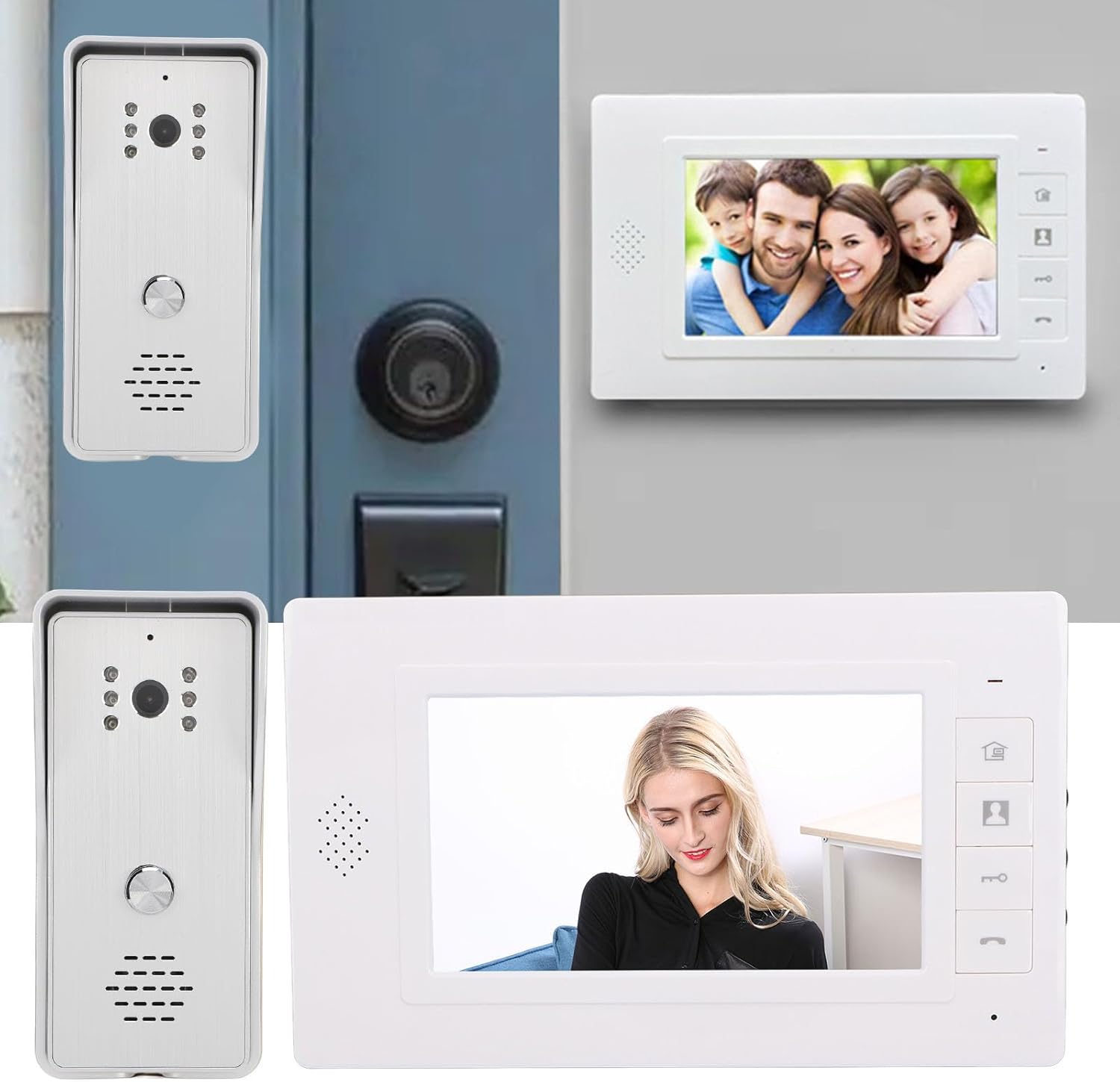
Figure 4.1: Example Installation.
4.1 Outdoor Unit Installation
- Choose a suitable location near your entrance, ensuring the camera has a clear view and is protected from direct heavy rain (the included rain cover provides additional protection).
- Mount the rain cover to the wall using the expansion screws.
- Secure the outdoor camera unit inside the rain cover using the metal screws.
- Ensure the unit is at an appropriate height for visitors to easily reach the call button and for the camera to capture faces clearly.
4.2 Indoor Unit Installation
- Select a convenient indoor location, such as a hallway or living room, where the monitor is easily accessible.
- Mount the provided mounting bracket to the wall using screws.
- Hang the indoor monitor unit onto the mounting bracket.
4.3 Wiring Connection
Connect the indoor and outdoor units using the provided 4-wire connection cables. Ensure all connections are secure and follow the wiring diagram provided in the detailed installation guide (not included in this general manual, refer to product packaging for specific diagrams).
- Connect one end of the 4-wire cable to the outdoor unit's wiring terminals.
- Route the cable to the indoor unit's location.
- Connect the other end of the 4-wire cable to the indoor unit's wiring terminals.
- If connecting an electronic door lock, connect the lock's wires to the designated terminals on the indoor unit (refer to specific wiring diagram).
- Plug the power adapter into the indoor monitor unit and then into a standard electrical outlet.
Note: Always ensure power is disconnected before making any wiring connections to prevent electrical shock or damage to the system.
5. Operating Instructions
5.1 Answering a Call
- When a visitor presses the call button on the outdoor unit, the indoor monitor will ring and display the visitor's image.
- Press the Answer Key (phone icon) on the indoor monitor to establish two-way audio communication.
- To end the conversation, press the Hang Up Key (phone icon again).
5.2 Monitoring the Outdoor Area
You can view the outdoor area at any time without a visitor pressing the call button.
- Press the Monitor Key (camera icon) on the indoor monitor.
- The screen will display the live feed from the outdoor camera.
- Press the Monitor Key again or the Hang Up Key to exit monitoring mode.
5.3 Unlocking the Door
If an electronic door lock is connected to the system, you can unlock it remotely.
- During a call or while monitoring, press the Unlock Key (key icon) on the indoor monitor.
- The connected door lock will activate, allowing the visitor entry.
5.4 Adjusting Settings
The indoor monitor allows adjustment of display and audio settings.
- Press the Menu Key (house icon) to access the settings menu.
- Use the side adjustment dials to modify Brightness, Color Contrast, and Sound Volume.
- The system also offers different ringtone choices, which can be selected via the menu.
5.5 Multi-Device Connectivity
This system supports multiple indoor monitors. All connected monitors can view, listen, and communicate with the outdoor unit, and unlock the door.
6. Maintenance
Regular maintenance ensures the longevity and optimal performance of your intercom system.
- Cleaning: Use a soft, dry cloth to clean the indoor monitor screen and outdoor camera lens. Avoid abrasive cleaners or solvents.
- Outdoor Unit: Periodically check the outdoor unit and its rain cover for any debris, dirt, or spiderwebs that might obstruct the camera view or microphone.
- Wiring: Ensure all wiring connections remain secure and free from damage.
- Power: Do not expose the power adapter to moisture or extreme temperatures.
7. Troubleshooting
If you encounter issues with your intercom system, refer to the following common problems and solutions:
| Problem | Possible Cause | Solution |
|---|---|---|
| No image on indoor monitor | Loose wiring connection; Power issue; Damaged camera/monitor. | Check all 4-wire connections; Ensure power adapter is plugged in and functional; Contact support if units are damaged. |
| No audio during communication | Volume too low; Loose wiring; Damaged speaker/microphone. | Adjust volume using side dial; Check 4-wire connections; Contact support. |
| Door lock not activating | Incorrect wiring to lock; Lock malfunction; Power issue to lock. | Verify lock wiring according to diagram; Test the lock independently; Ensure adequate power supply to the lock. |
| Poor night vision quality | Obstructed IR lights; Dirty camera lens. | Clean the camera lens and ensure IR lights are clear of obstructions. |
If the problem persists after attempting these solutions, please contact customer support for further assistance.
8. Specifications
Technical specifications for the Cuifati Wired Video Intercom System (Model Cuifatisw45mt1g7g-14):

Figure 8.1: Product Dimensions.
- Item Type: Smart Video Intercom System
- Material: ABS
- Wiring Method: 4-wire
Outdoor Camera Unit
- Camera Sensor: 1/4 HD CMOS
- Light Source: 6 Infrared Lights
- Resolution: 800 x 600 pixels
- Viewing Angle: 120 degrees
- Dimensions: Approximately 134mm (H) x 59mm (W) x 39mm (D)
Indoor Monitor Unit
- Screen: 7-inch TFT LCD
- Resolution: 800 x 480 pixels
- Adjustable Settings: Brightness, Volume, Contrast
- Dimensions: Approximately 150mm (H) x 245mm (W) x 23mm (D)
General
- Product Dimensions (Overall): 26 x 16 x 10 cm
- Product Weight: 874 grams
- Manufacturer: Cuifati
- ASIN: B0DD1HJCQS
- Country of Origin: China
9. Warranty and Support
For warranty information, please refer to the documentation provided at the time of purchase or contact your retailer. For technical support or further assistance, please reach out to Cuifati customer service through the contact information provided with your product or on the official Cuifati website.


