
NICGIGA FS2420GP
NICGIGA 26 Port PoE Switch (Model FS2420GP) User Manual
Model: FS2420GP | Brand: NICGIGA
1. Introduction
This manual provides detailed instructions for the installation, operation, and maintenance of your NICGIGA 26 Port PoE Switch. This unmanaged switch features 24 PoE+ ports with a total power budget of 400W, and 2 Gigabit uplink ports. It is designed for reliable network connectivity and power delivery to compatible devices.
Key features include IEEE802.3af/at compliance, automatic detection of Powered Devices (PDs), VLAN isolation, 250m extend mode, 4KV lightning protection, and a sturdy metal housing suitable for desktop or 19-inch rack mounting. The switch is plug-and-play, requiring no complex configuration.
2. Package Contents
Please verify that all items listed below are included in your package. If any item is missing or damaged, please contact customer support.
- NICGIGA 26 Port PoE Switch (Model FS2420GP)
- Power Adapter
- Rack Mount Kit (2 brackets)
- Pack of Screws
- Quick Start Guide

Image: The package contents for the NICGIGA 26 Port PoE Switch, showing the switch unit, power adapter, rack mount brackets, mounting screws, and a quick start guide.
3. Product Overview
3.1 Front Panel

Image: Front panel of the NICGIGA 26 Port PoE Switch, highlighting the 24 10/100Mbps PoE ports (ports 1-24) and the 2 100/1000Mbps uplink ports (ports 25-26). It also indicates the total power budget of 400W and 30W per PoE port.
- PoE Ports (1-24): 10/100Mbps Ethernet ports with Power over Ethernet (PoE+) capability. Each port can deliver up to 30W, with a total power budget of 400W for all PoE ports.
- Uplink Ports (25-26): 100/1000Mbps Gigabit Ethernet ports for connecting to a router, NVR, or other network devices. These ports do not provide PoE.
- LED Indicators: Status LEDs for power, link/activity, and PoE status (not explicitly shown in image but standard).
- Mode Switch: A physical switch to toggle between Default and Extend modes.
3.2 Rear Panel
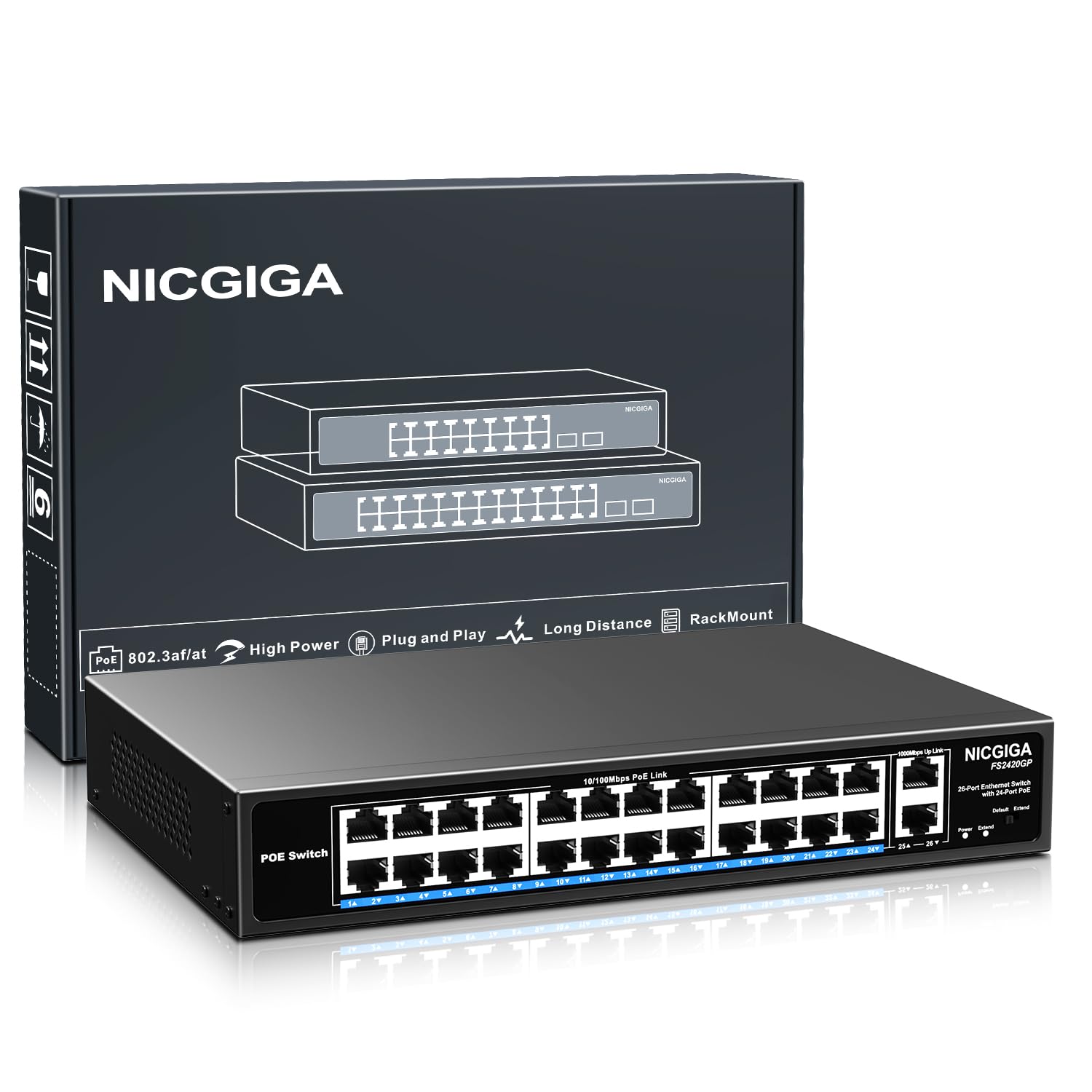
Image: Rear panel of the NICGIGA 26 Port PoE Switch, showing the AC power input (110-240V) and the built-in 400W power supply.
- AC Power Input: Connect the provided power adapter here. The switch supports 110-240V AC input.
3.3 Key Features
- 26-Port PoE+ Switch: 24 PoE+ ports (IEEE802.3af/at compliant) with 400W total power budget, plus 2 Gigabit uplink ports.
- VLAN Isolation: Ports 1-24 are isolated from each other but can communicate with the uplink ports (25-26) to reduce network broadcast storms and enhance security.
- 250m Extend Mode: When enabled, PoE ports can transmit data and power up to 250 meters at 10Mbps, ideal for long-distance deployments.
- Unmanaged Plug-and-Play: No software or configuration required for setup.
- 4KV Lightning Protection: Protects the device from electrical surges.
- Sturdy Metal Housing: Durable design for desktop or 19-inch rack mounting.
- Fanless Design: Provides silent operation.

Image: Automatic Induction feature, demonstrating how the switch automatically detects and supplies power to PoE devices (IP Phone, IP Camera, Wireless AP) and provides data connection to non-PoE devices (Router, Printer, NVR).

Image: One Key VLAN feature, illustrating that ports 1-24 are isolated from each other but can communicate with uplink ports 25-26, improving network security.

Image: Extend Mode functionality, demonstrating how the switch can extend PoE link distance up to 250m at 10Mbps, compared to the default 100m at 10/100Mbps.
4. Setup Instructions
4.1 Placement
The NICGIGA 26 Port PoE Switch can be placed on a desktop or mounted in a standard 19-inch rack.
- Ensure adequate ventilation around the switch to prevent overheating.
- Avoid placing the switch near strong electromagnetic interference sources.
- Keep the switch away from water or damp environments.
4.2 Rack Mounting (Optional)
To install the switch in a 19-inch rack:
- Attach the two rack-mount brackets to the sides of the switch using the provided screws.
- Secure the switch into the 19-inch rack using appropriate rack screws (not always included, check your rack's hardware).

Image: The NICGIGA 26 Port PoE Switch shown with rack mount brackets, illustrating how it fits into a standard 19-inch rack. Dimensions of the switch are also indicated.
4.3 Connecting the Switch
- Power Connection: Connect the power adapter to the AC power input on the rear panel of the switch, then plug the other end into a power outlet. The power LED should illuminate.
- Uplink Connection: Connect your router, modem, or main network device to one of the Gigabit uplink ports (25 or 26) using a standard Ethernet cable.
- Device Connections: Connect your PoE-compatible devices (e.g., IP cameras, IP phones, wireless access points) to any of the PoE ports (1-24) using Ethernet cables. The switch will automatically detect and power these devices.
- Non-PoE Devices: You can also connect non-PoE network devices (e.g., computers, printers) to the PoE ports. The switch will provide data connectivity without power.

Image: The NICGIGA PoE switch connected to an IP camera and a laptop, illustrating how it provides both power and data to PoE devices and data to standard network devices.
5. Operating Instructions
5.1 Power On
Once the power adapter is connected, the switch will power on automatically. The power indicator LED will light up, indicating the device is operational.
5.2 LED Indicators
| LED Name | Status | Description |
|---|---|---|
| Power | On | The switch is powered on. |
| Link/Act (Per Port) | On | A device is connected to the port. |
| Flashing | Data is being transmitted or received. | |
| PoE (Per PoE Port) | On | PoE power is being supplied to the connected device. |
| Flashing | PoE fault or overload detected. |
5.3 Mode Switch (Default/Extend)
The switch features a physical mode switch on the front panel. This switch allows you to toggle between two operational modes:
- Default Mode: Standard operation. PoE ports (1-24) operate at 10/100Mbps, and data/power transmission distance is up to 100 meters. VLAN isolation is active, meaning ports 1-24 are isolated from each other but can communicate with uplink ports.
- Extend Mode: When enabled, PoE ports (1-24) operate at 10Mbps, and data/power transmission distance is extended up to 250 meters. VLAN isolation remains active. This mode is useful for connecting IP cameras or other devices over longer distances where high bandwidth is not critical.
To change modes, simply slide the switch to the desired position. No reboot is required, but connected devices may briefly lose connection as the port mode adjusts.
6. Maintenance
- Cleaning: Use a soft, dry cloth to clean the exterior of the switch. Do not use liquid or aerosol cleaners.
- Ventilation: Ensure that the ventilation openings are not blocked to allow for proper heat dissipation. The switch features a fanless design for silent operation, relying on its metal casing for cooling.
- Cable Management: Keep network cables organized and free from kinks or excessive bends to ensure optimal performance and prevent damage.
- Power Supply: Use only the provided power adapter. If a replacement is needed, ensure it matches the original specifications.
- Environmental Conditions: Operate the switch within the recommended temperature and humidity ranges specified in the technical specifications.
7. Troubleshooting
| Problem | Possible Cause | Solution |
|---|---|---|
| No Power LED | Power adapter not connected or faulty. | Ensure the power adapter is securely connected to the switch and a working power outlet. Test the outlet with another device. |
| No Link/Act LED | Ethernet cable disconnected or faulty; connected device is off or faulty. | Check the Ethernet cable connection at both ends. Try a different cable. Ensure the connected device is powered on and functioning correctly. |
| No PoE LED (PoE port) | Connected device is not PoE-compatible; device requires more power than available; cable issue. | Verify the device is IEEE802.3af/at compliant. Check the power requirements of the device against the switch's per-port and total power budget. Ensure the Ethernet cable is functioning. |
| Network Slowdown | High network traffic; incorrect mode (e.g., Extend mode for high bandwidth). | If using Extend Mode, remember it limits speed to 10Mbps. Switch back to Default Mode for 10/100Mbps speeds if needed. Check for excessive network activity or faulty devices. |
If you encounter issues not covered here or require further assistance, please contact NICGIGA customer support.
8. Specifications
| Feature | Detail |
|---|---|
| Brand | NICGIGA |
| Model Number | FS2420GP |
| Number of Ports | 26 (24 PoE+, 2 Gigabit Uplink) |
| PoE Standard | IEEE 802.3af/at |
| Maximum Power (Total) | 400 Watts |
| Maximum Power (Per PoE Port) | 30 Watts |
| Data Transfer Rate | 10/100Mbps (PoE Ports), 100/1000Mbps (Uplink Ports) |
| Switch Type | Unmanaged |
| Extend Mode Distance | Up to 250m (at 10Mbps) |
| Lightning Protection | 4KV |
| Case Material | Metal |
| Installation | Desktop or 19-inch Rack Mount |
| UPC | 790885826238 |
9. Warranty and Support
9.1 Warranty Information
This NICGIGA PoE Switch comes with a 1 Year Warranty from the date of purchase. This warranty covers manufacturing defects and malfunctions under normal use. It does not cover damage caused by misuse, accidents, unauthorized modifications, or natural disasters.
Please retain your proof of purchase for warranty claims.
9.2 Customer Support
For any questions, technical assistance, or warranty inquiries regarding your NICGIGA 26 Port PoE Switch, please contact our customer support team. You can typically find contact information on the NICGIGA official website or through your purchase platform.
Our team is dedicated to providing reliable support and ensuring your satisfaction with our products.
Related documentsFS2420GP


Ask a question about this manual
Ask about setup, troubleshooting, compatibility, parts, safety, or missing instructions. Manuals+ will review the question and use this page’s manual context to help answer it.