1. Introduction
This manual provides detailed instructions for the safe and effective operation of the YXJPP ET826 Digital Multimeter Oscilloscope. The ET826 is a versatile 2-in-1 instrument combining the functions of a digital multimeter and an oscilloscope, designed for electrical measurement and waveform analysis.
Key features include:
- 200k high-speed A/D sampling with 4000 counts auto-range display.
- Graphical waveform display capability.
- Ability to store 100 sets of data and 10 waveform records.
- One-button automatic waveform capture.
- Relative value measurement for eliminating lead resistance and distributed capacitance.

Image 1.1: The YXJPP ET826 device highlighting its innovative 2-in-1 functionality as a multimeter and oscilloscope.
2. Safety Information
WARNING: To avoid electric shock or personal injury, and to prevent damage to the meter or to the equipment under test, observe the following safety rules:
- Always ensure the meter is in good working condition before use.
- Do not apply more than the rated voltage, as marked on the meter, between the terminals or between any terminal and earth ground.
- Use caution when working with voltages above 30V AC RMS, 42V peak, or 60V DC. These voltages pose a shock hazard.
- Always connect the common (COM) test lead before connecting the live test lead. When disconnecting, disconnect the live test lead first.
- Ensure the test leads are properly seated and free from damage.
- Do not operate the meter with the battery cover or case open.
- Replace the battery as soon as the low battery indicator appears to ensure accurate readings.
- Do not use the meter if it operates abnormally. Protection may be impaired.
- Adhere to local and national safety codes.
3. Package Contents
Upon unpacking, please verify that all items listed below are present and undamaged:
- 1 x YXJPP ET826 Digital Multimeter Oscilloscope
- 1 Pair x Test Leads (Red and Black)
- User Manual (This document)
Note: 3 x 1.5V AA batteries are required for operation and are not included in the package.
4. Product Overview
The ET826 features a clear LCD display and a rotary dial for function selection. Understanding the layout of the device is crucial for proper operation.

Image 4.1: Front view of the ET826 Digital Multimeter Oscilloscope, showing the display, function buttons, rotary dial, and input jacks.
4.1. Display
The device features a 128x64 dot-graphics LCD display with a size of 60 x 40mm (2.4 x 1.6 inches). It provides a 4000-count digital readout and can display graphical waveforms.

Image 4.2: The ET826 display showing historical and real-time data simultaneously, illustrating changes in measured signals.
4.2. Function Buttons
- AUTO: Automatic ranging mode.
- DIS: Display mode selection (e.g., digital, graphical).
- REL: Relative value measurement.
- SELE: Function selection within a rotary switch position.
- HOLD: Data hold function.
4.3. Rotary Dial
The central rotary dial is used to select the primary measurement function (e.g., AC Voltage, DC Current, Resistance, Capacitance, Oscilloscope mode).
4.4. Input Jacks
- 10A: Input for high current measurements (up to 10A).
- mAμF: Input for milliampere, microampere, and capacitance measurements.
- VΩCap: Input for voltage, resistance, and diode/continuity measurements.
- COM: Common (negative) input for all measurements.
5. Setup
5.1. Battery Installation
- Ensure the meter is turned OFF.
- Locate the battery compartment on the back of the meter.
- Unscrew the battery compartment cover.
- Insert three (3) 1.5V AA batteries, observing the correct polarity (+ and -).
- Replace the battery compartment cover and secure it with the screw.
5.2. Connecting Test Leads
Always connect the black test lead to the COM jack. Connect the red test lead to the appropriate input jack based on the measurement type:
- For Voltage, Resistance, Capacitance, Diode, Continuity: Connect the red lead to the VΩCap jack.
- For Current (mA/μA): Connect the red lead to the mAμF jack.
- For High Current (10A): Connect the red lead to the 10A jack.

Image 5.1: The ET826 Multimeter Oscilloscope shown with its red and black test leads connected to the appropriate input jacks.
6. Operating Modes
The ET826 combines multimeter and oscilloscope functionalities. Select the desired mode using the rotary dial.

Image 6.1: Illustration of the ET826's dual functionality as both a multimeter and an oscilloscope, emphasizing ease of operation.
6.1. Multimeter Functions
Turn the rotary dial to the desired measurement function. The meter will typically default to auto-ranging. Press the SELE button to switch between AC/DC, or other sub-functions if available within a single dial position.
- Voltage (V~ / V-): Measures AC or DC voltage.
- Current (A~ / A-): Measures AC or DC current.
- Resistance (Ω): Measures electrical resistance.
- Capacitance (mF): Measures capacitance.
- Frequency (Hz%): Measures frequency and duty cycle.
- Diode Test (->|): Tests diodes.
- Continuity (sound wave icon): Checks for circuit continuity with an audible beep.

Image 6.2: Visual representation of various functions available on the ET826, including Oscilloscope, Voltage, Current, Resistance, Capacitance, Frequency, Relative Value, Diode, and Continuity.
6.2. Oscilloscope Function
To use the oscilloscope function, turn the rotary dial to the "OSC" position. The ET826 features a one-button automatic waveform capture, allowing direct measurement of waveforms without complex probe adjustments.
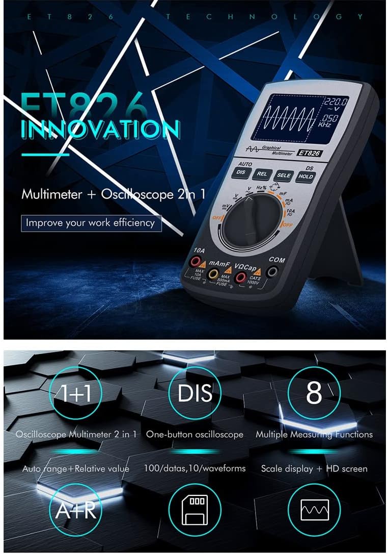
Image 6.3: The ET826 in oscilloscope mode, demonstrating its ability to measure waveforms directly with a single button press.
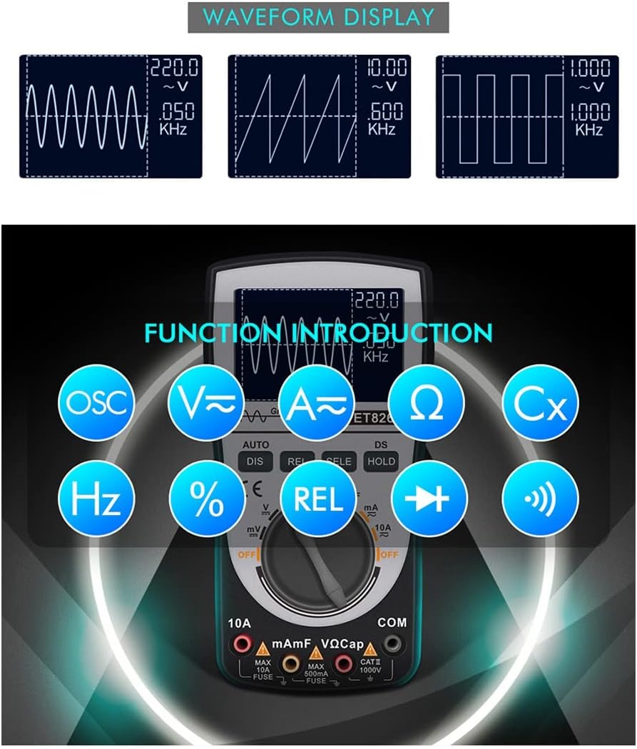
Image 6.4: Examples of different waveforms (sine, triangle, square) displayed on the ET826 screen, indicating its waveform analysis capability.
6.3. Auto Range and Relative Value
The AUTO button enables automatic ranging, which helps prevent damage to the meter from incorrect range selection. The REL button activates relative value measurement, which can eliminate the influence of lead resistance and distributed capacitance for more accurate readings.
Image 6.5: The ET826 display showing both auto-ranging functionality and the relative value measurement feature.
7. Data Storage and Recall
The ET826 can store up to 100 sets of measurement data and 10 waveform records. This feature allows for later review and analysis of measurements.
Image 7.1: The ET826 display indicating its data storage capability, showing multiple sets of data and waveforms.
Refer to the on-screen prompts or specific button combinations (often involving the DIS or HOLD buttons in conjunction with SELE) to save and recall data. Detailed instructions for data management are typically found in the device's on-screen menu or quick reference guide.
8. Maintenance
8.1. Cleaning
Wipe the case with a damp cloth and mild detergent. Do not use abrasives or solvents. Ensure the meter is completely dry before use.
8.2. Battery Replacement
Replace the batteries when the low battery indicator appears on the display. Refer to Section 5.1 for battery installation instructions.
8.3. Fuse Replacement
If the current measurement function fails, the fuse may need replacement. This procedure should only be performed by qualified personnel. Refer to the specifications for the correct fuse type and rating. Always disconnect test leads and power before opening the meter case.
9. Troubleshooting
- Meter does not power on: Check battery installation and ensure batteries are fresh.
- No reading or incorrect reading:
- Ensure test leads are correctly connected to the meter and the circuit under test.
- Verify the rotary dial is set to the correct function.
- Check for damaged test leads.
- For current measurements, check the fuse.
- Display shows "OL" (Overload): The measured value exceeds the selected range. If in manual range, switch to a higher range. If in auto-range, the value is beyond the meter's maximum capability for that function.
- Oscilloscope waveform is unstable: Ensure proper connection to the circuit. Adjust time base or voltage scale if available, or use the one-button auto-capture feature.
10. Specifications
| Parameter | Value |
|---|---|
| Display | LCD, 128x64 dot-graphics, 4000 counts |
| LCD Size | 60 x 40mm (2.4 x 1.6in) |
| Analog Bandwidth | ACV/DCV/ACA/20kHz |
| Sampling Rate | 200k high-speed A/D |
| Input Resistance | 10MΩ |
| Power | 3 x 1.5V AA battery (not included) |
| Auto Sleep | Yes (15 minutes without operation) |
| Power Consumption | Approx. 40mA |
| Data Storage Capacity | 100 groups of data |
| Waveform Record Capacity | 10 groups of waveforms |
| Operation Environment | 0°C ~ +40°C; < 75%RH |
| Storage Environment | -10°C ~ +60°C; < 90%RH |
| Dimensions | 160 x 83 x 32mm |
| Material | ABS |
11. Warranty and Support
For warranty information and technical support, please refer to the documentation provided at the point of purchase or contact YXJPP customer service. Keep your purchase receipt as proof of purchase for warranty claims.
Manufacturer: YXJPP