
1. Introduction
This manual provides essential information for the safe and efficient operation of the Wisoqu SKI780-5D5G-4 Frequency Converter. Please read this manual thoroughly before installation, operation, or maintenance to ensure proper use and to prevent damage to the device or injury to personnel. Keep this manual for future reference.
2. Safety Information
Frequency converters operate with high voltages and can cause severe injury or death if not handled correctly. Observe all safety precautions.
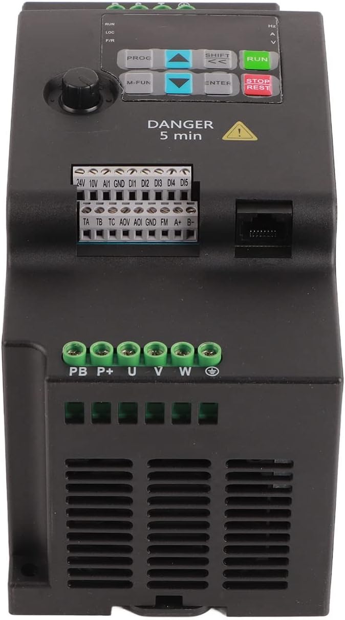
- Electrical Hazard: The device contains high voltage components. Do not open the cover or touch internal parts when power is applied or shortly after power is removed. Wait at least 5 minutes after disconnecting power before servicing, as indicated by the 'DANGER 5 min' warning on the unit.
- Qualified Personnel: Installation, wiring, and maintenance must be performed by qualified electrical personnel only.
- Grounding: Ensure the frequency converter is properly grounded to prevent electric shock.
- Proper Wiring: Verify all wiring connections are correct and secure before applying power. Incorrect wiring can lead to malfunction or damage.
- Environmental Conditions: Do not expose the unit to water, excessive dust, corrosive gases, or extreme temperatures.
- Emergency Stop: Ensure an accessible emergency stop mechanism is in place for the connected motor and system.
3. Product Overview
3.1 Features
- Built-in braking unit, requiring only an external braking resistor for fast forward and reverse rotation switching.
- RS485 communication support with multiple optional protocols and linkage synchronization control.
- Multi-segment operation with 16-segment programmable multi-speed control, offering various operating modes.
- Wide output frequency range, including a low frequency mode of 0-500Hz.
- PID control, suitable for applications such as constant pressure water supply and wind pressure constant pressure control.
3.2 Components and Layout



4. Specifications
The following table details the technical specifications of the SKI780-5D5G-4 Frequency Converter:
| Parameter | Value |
|---|---|
| Model | SKI780-5D5G-4 |
| Application Range | Universal |
| Power Phase Number | Three Phase |
| Power Supply Voltage | Three-phase AC380V 50/60Hz |
| Output Voltage | Three-phase AC380V |
| Adapted Motor Power | 5.5 kW |
| Rated Current | 13 A |
| Control Method | Current Vector |
| Output Voltage Regulation Mode | PWM Control |
| Product Size (L*W*H) | Approx. 180 * 115 * 95mm / 7.1 * 4.5 * 3.7in |
| Panel Opening Size | Approx. 61 * 81mm / 2.4 * 3.2in |
| Weight | Approx. 1.5kg / 3.3 lb |
| Item Model Number | Wisoquc1d842niux |
5. Setup and Installation
Proper installation is crucial for the performance and safety of the frequency converter. It is recommended that installation be performed by a qualified electrician.
5.1 Mounting
- Mount the unit vertically on a stable, non-flammable surface.
- Ensure adequate ventilation space around the unit (refer to Figure 3.2.4 for dimensions). Do not obstruct cooling vents.
- Avoid locations with direct sunlight, high humidity, excessive dust, or corrosive gases.
5.2 Wiring
Refer to the terminal labels on the unit (Figure 3.2.1 and 3.2.2) for correct connections.
- Power Input (RST): Connect the three-phase AC380V 50/60Hz power supply to the R, S, T terminals.
- Motor Output (UVW): Connect the three-phase motor to the U, V, W terminals.
- Grounding: Connect the ground terminal (⊗) to a reliable earth ground.
- Braking Resistor (PB P+): If using an external braking resistor for fast stopping, connect it to the PB and P+ terminals.
- Control Terminals: Utilize the control terminals (24V, 10V, AI1, GND, DI1-DI5, 1A, 1B, 1C, AO1, GND, FM, A+, B-) for external control signals, analog inputs, relay outputs, and RS485 communication as required by your application. Consult the detailed wiring diagram in the included physical user manual for specific connections.
After wiring, double-check all connections for tightness and correctness before applying power.
6. Operating Instructions
This section provides general guidance on operating the frequency converter. Detailed parameter settings and advanced functions are covered in the comprehensive physical user manual.
6.1 Basic Operation
- Power On: Apply power to the unit. The display will illuminate, showing the current operating status or frequency.
- RUN Button: Press the RUN button to start the motor. The motor will accelerate to the set frequency.
- STOP/REST Button: Press the STOP/REST button to stop the motor. The motor will decelerate and come to a halt.
- Frequency Adjustment: Use the ▲ (Up) and ▼ (Down) arrow buttons to adjust the output frequency (and thus motor speed) when in manual control mode.
6.2 Control Panel Buttons
- PROG: Enters or exits the parameter setting mode.
- SHIFT (<<): Shifts the cursor position during parameter editing or views different parameters.
- M-FUN: Accesses multi-function menus or specific function settings.
- ENTER: Confirms parameter settings or enters sub-menus.
6.3 Advanced Functions
- Multi-segment Operation: The unit supports 16-segment programmable multi-speed control. Refer to the parameter settings section in the full manual to configure these speeds.
- PID Control: For applications requiring precise control (e.g., constant pressure), configure the PID parameters through the control panel.
- RS485 Communication: The VFD can be integrated into a larger control system via RS485. Consult the communication protocol details in the full manual for setup.
7. Maintenance
Regular maintenance ensures the longevity and reliable operation of your frequency converter.
- Power Off Before Maintenance: Always disconnect all power to the unit and wait at least 5 minutes for capacitors to discharge before performing any maintenance.
- Cleaning: Periodically clean the exterior of the unit and ensure cooling vents are free from dust and debris. Use a soft, dry cloth. Do not use liquid cleaners.
- Inspection: Regularly inspect wiring connections for tightness and signs of wear or damage. Check for any unusual noises or smells during operation.
- Environmental Check: Ensure the operating environment remains within specified temperature and humidity ranges.
8. Troubleshooting
If you encounter issues with your frequency converter, refer to the following basic troubleshooting steps. For complex problems or error codes, consult the detailed troubleshooting guide in the full user manual.
- No Power/Display Off: Check the main power supply and all input wiring connections (R, S, T). Ensure the circuit breaker or fuse is not tripped.
- Motor Not Running: Verify the RUN command is active. Check motor wiring (U, V, W) and ensure the motor is not overloaded or mechanically jammed. Confirm the frequency setting is not zero.
- Overload/Overcurrent Trip: Reduce the motor load. Check for short circuits in motor wiring. Verify motor parameters are correctly set in the VFD.
- Overvoltage/Undervoltage Trip: Check the input power supply voltage. Ensure the braking resistor (if used) is correctly sized and connected.
- Unusual Noise: Check for loose connections or mounting. Ensure proper ventilation to prevent overheating.
If the problem persists after basic troubleshooting, contact technical support.
9. Package Contents
Upon opening the package, please verify that all items are present and undamaged:
- 1 x Wisoqu SKI780-5D5G-4 Frequency Converter
- 1 x User Manual (this document, or a more comprehensive version)
10. Warranty and Support
For warranty information, technical support, or service inquiries, please refer to the contact details provided with your purchase or visit the official Wisoqu store online. Keep your purchase receipt as proof of purchase.
Visit the Wisoqu Store: Wisoqu Official Store