1. Introduction
The Irfora FY375 is a multifunctional digital clamp meter designed for accurate and reliable electrical measurements. It features a 5999-count LCD display and can measure AC/DC current, AC/DC voltage, resistance, capacitance, frequency, temperature, diode, and continuity. It also includes Non-Contact Voltage (NCV) detection and live wire identification for enhanced safety and convenience.

Figure 1: Irfora FY375 Digital Clamp Meter
2. Safety Information
Please read and understand all safety information before operating this meter. Improper use can result in electric shock, injury, or damage to the meter or equipment under test.
- Always adhere to local and national safety codes.
- Do not use the meter if it appears damaged or if the test leads are damaged.
- Do not apply more than the rated voltage, as marked on the meter, between the terminals or between any terminal and earth ground.
- Use extreme caution when working with voltages above 60V DC or 30V AC RMS. Such voltages pose a shock hazard.
- Remove the test leads from the meter before opening the battery cover.
- Replace the battery immediately when the low battery indicator appears.
- Do not operate the meter in explosive gas, vapor, or dusty environments.
- Always use the correct function and range for measurements.
- Ensure the meter is switched off before connecting or disconnecting test leads to the circuit.
3. Product Overview
Familiarize yourself with the components of your Irfora FY375 Digital Clamp Meter.

Figure 2: Labeled Components of the FY375 Clamp Meter
- NCV Detector: For non-contact voltage detection.
- Transformer Jaws: Used for AC/DC current measurement without breaking the circuit. Jaw size: 28mm.
- Trigger: Opens the transformer jaws.
- Flashlight: Illuminates the measurement area.
- LCD Display: 5999 counts display for measurement readings. Screen size: 53x35mm.
- Date Hold and Flashlight Button: Press to hold the current reading; long press to activate/deactivate flashlight.
- NCV/LIVE Switching Key: Toggles between NCV and Live Wire detection modes.
- ON/OFF Switch and Function Switching Button: Powers the device on/off and cycles through measurement functions.
- "COM" Jack: Common input terminal for test leads (black).
- "INPUT" Jack: Positive input terminal for test leads (red).

Figure 3: Jaw Size and LCD Display Detail
4. Setup
4.1 Battery Installation
The FY375 meter requires two 1.5V AAA batteries (not included).
- Ensure the meter is powered off and disconnect any test leads.
- Locate the battery compartment cover on the back of the meter.
- Use a screwdriver to open the battery compartment.
- Insert two AAA batteries, observing the correct polarity (+ and -).
- Replace the battery compartment cover and secure it with the screw.
4.2 Connecting Test Leads
For measurements requiring test leads (voltage, resistance, capacitance, frequency, diode, continuity, temperature), connect them as follows:
- Insert the black test lead into the "COM" (common) jack.
- Insert the red test lead into the "INPUT" jack.

Figure 4: Connecting Test Leads
5. Operating Instructions
5.1 Power On/Off and Function Selection
- To power on the meter, press the ON/OFF /SEL button.
- To cycle through measurement functions (e.g., AC Voltage, DC Voltage, Resistance), short press the ON/OFF /SEL button. The selected function will be indicated on the LCD.
- To power off the meter, long press the ON/OFF /SEL button. The meter also features an auto-shutdown function after 10 minutes of inactivity.
5.2 AC/DC Current Measurement (Clamp Jaw)
Use the clamp jaws to measure AC or DC current without breaking the circuit.
- Power on the meter and select the AC Current (A~) or DC Current (A-) function using the ON/OFF /SEL button.
- Press the trigger to open the clamp jaws.
- Enclose only one conductor of the circuit within the jaws. Ensure the jaws are fully closed.
- Read the current value on the LCD display.
5.3 Voltage, Resistance, Capacitance, Frequency, Diode, Continuity (Test Leads)
For these measurements, connect the test leads as described in Section 4.2.
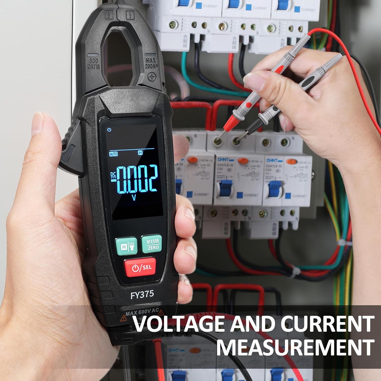
Figure 5: Voltage Measurement in a Circuit Panel
- Power on the meter and select the desired function (e.g., V~ for AC Voltage, V- for DC Voltage, Ω for Resistance, etc.) using the ON/OFF /SEL button.
- Connect the test leads to the circuit or component under test.
- Read the measurement on the LCD display.

Figure 6: True RMS Measurement Example
5.4 NCV (Non-Contact Voltage) Test
The NCV function detects AC voltage without physical contact.
- Press the NCV/LIVE ZERO button to enter NCV mode.
- Bring the NCV detector part of the meter close to the wire or conductor.
- The meter will emit an audible beep and visual alarm (LED flash) if AC voltage is detected.
5.5 Live Wire Detection
This function helps identify live wires.
- Press the NCV/LIVE ZERO button to cycle to Live Wire mode.
- Use the red test lead to touch the conductor.
- The meter will indicate if the wire is live.
5.6 Temperature Measurement
Use the included thermocouple for temperature measurements.

Figure 7: Temperature Measurement
- Connect the thermocouple to the meter's input jacks (red to INPUT, black to COM).
- Select the temperature function (℃/℉) using the ON/OFF /SEL button.
- Place the thermocouple tip on or near the object whose temperature is to be measured.
- Read the temperature on the LCD display.
5.7 Data Hold and Flashlight
- Data Hold: Short press the H / Flashlight button to freeze the current reading on the display. Press again to release.
- Flashlight: Long press the H / Flashlight button to turn the built-in flashlight on or off.
6. Maintenance
6.1 Cleaning
Wipe the meter with a dry, soft cloth. Do not use abrasives or solvents.
6.2 Battery Replacement
When the low battery indicator appears on the display, replace the batteries as described in Section 4.1. Remove batteries if the meter is not used for extended periods.
6.3 Storage
Store the meter in a cool, dry place, away from direct sunlight and extreme temperatures. The storage environment should be 14℉~122℉ (-10℃~50℃, <70%RH).
7. Troubleshooting
- Meter does not power on: Check battery installation and ensure batteries are not depleted.
- No reading or incorrect reading: Ensure test leads are properly connected, the correct function is selected, and the circuit is live (if applicable). Check for damaged test leads.
- "OL" displayed: Indicates an over-range condition. The measured value exceeds the meter's maximum range for the selected function.
- Inaccurate temperature reading: Ensure the thermocouple is correctly connected and making good contact with the object.
8. Specifications

Figure 8: Product Dimensions
| Parameter | Range | Resolution |
|---|---|---|
| Resistance | 600Ω/6kΩ/60kΩ/600kΩ/6MΩ/60MΩ | 0.1Ω/0.001kΩ/0.01kΩ/0.1kΩ/0.001MΩ/0.01MΩ |
| Capacitance | 6nF/60nF/600nF/6uF/60uF/600uF/6mF/60mF | 0.001nF/0.01nF/0.1nF/0.001uF/0.01uF/0.1uF/0.001mF/0.01mF |
| Frequency | 40Hz/400Hz/1KHz | 0.01Hz/0.1Hz/0.001KHz |
| Temperature | -20℃~1000℃/-4℉~1832℉ | 1℃/2℉ |
| AC Current | 60A/200A | 0.01A/0.1A |
| DC Current | 200A | 0.1A |
General Specifications
- Display: 5999 counts LCD display
- Sampling Speed: Approx. 3 times / second
- Over-Indication: "OL" on LCD
- Battery Low Voltage Indication: Yes
- Input Polarity Indication: "-" automatically displayed
- Power Supply: 2 x 1.5V AAA batteries (not included)
- Auto Shutdown: 10 minutes without signal input
- Diode Test: Yes
- Continuity Test: Buzzer sounds if resistance < 50Ω
- NCV: Yes
- Live Wire Detection: Yes
- Data Hold: Yes
- Flashlight: Yes
- Maximum Permissible Voltage: 600V DC or 600V AC RMS
- Use Environmental Conditions: 600V CAT. III Pollution degree: 2; Altitude <2000 m
- Working Environment: 32℉~104℉ (0~40℃, <80%RH, <10℃ non-condensing)
- Storage Environment: 14℉~122℉ (-10℃~50℃, <70%RH, remove the battery)
- Temperature Coefficient: 0.1 accuracy/℃ (<18℃ or >28℃)
- Material: ABS
- Item Size: 18 * 6.5 * 3 cm / 7.09 * 2.56 * 1.18 inch
- Item Weight: 149g / 5.28oz
9. Package Contents
- 1 x Irfora FY375 AC/DC Clamp Meter
- 2 x Test Leads
- 1 x Thermocouple
- 1 x Cloth Bag
- 1 x User Manual (English)
10. Warranty and Support
No specific warranty information is provided with this product. For technical support or inquiries, please refer to the retailer or manufacturer's contact information provided at the point of purchase.
