1. Introduction
Thank you for choosing the Irfora T58B Digital Multimeter. This instrument is a handheld, true RMS digital multimeter designed for accurate measurement of AC/DC voltage, AC/DC current, frequency, resistance, capacitance, and diodes. It is a versatile tool for solving industrial and household electrical problems, suitable for both DIY enthusiasts and professionals.
Please read this manual thoroughly before use to ensure safe and proper operation. Keep this manual for future reference.
2. Safety Information
Warning: To avoid electric shock or personal injury, and to prevent damage to the meter or the equipment under test, observe the following safety rules:
- Always ensure the meter is in the correct function and range for the measurement.
- Do not apply more than the rated voltage, as marked on the meter, between the terminals or between any terminal and earth ground.
- Use caution when working with voltages above 30V AC RMS, 42V peak, or 60V DC. Such voltages pose a shock hazard.
- Before making current measurements, ensure the meter's fuses are intact and the test leads are connected to the correct input jacks.
- Disconnect the test leads from the circuit before changing functions or ranges.
- Do not use the meter if it appears damaged or if the insulation on the test leads is compromised.
- Replace the battery as soon as the low battery indicator appears to avoid incorrect readings.
- Adhere to local and national safety codes.
3. Product Overview
The Irfora T58B Digital Multimeter features a robust design and a clear LCD display for easy readings.
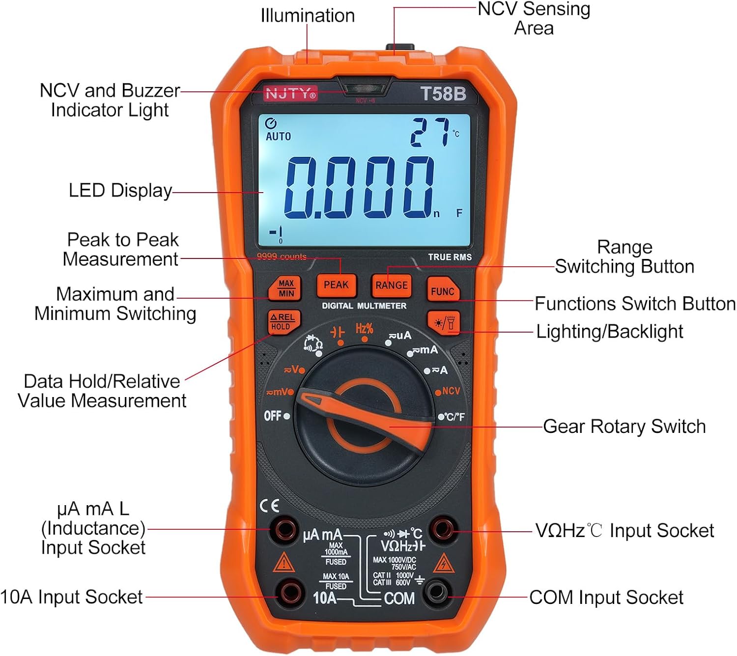
Figure 3.1: Front view of the Irfora T58B Digital Multimeter with labeled components. Key features include the LED Display, NCV and Buzzer Indicator Light, Gear Rotary Switch, Input Sockets, and various function buttons.

Figure 3.2: Dimensions of the Irfora T58B Digital Multimeter. The device measures approximately 187mm (7.36in) in height, 95mm (3.74in) in width, and 55mm (2.16in) in depth.

Figure 3.3: Rear view of the multimeter showing the 90-degree adjustable support stand and integrated storage slots for test leads, designed for convenience and protection.

Figure 3.4: Overview of the Irfora T58B Digital Multimeter's capabilities, including 9999 counts display, and measurement of current, resistance, capacitance, temperature, and frequency.
Key Features:
- 9999 Counts LCD Digital Display with Backlight
- True RMS Measurement
- Non-Contact Voltage (NCV) Detection
- Automatic Power Off
- Data Hold and Relative Value Measurement
- Flashlight Function for low-light conditions
- Measures AC/DC Voltage, AC/DC Current, Resistance, Capacitance, Frequency, and Temperature
- Diode and Continuity Test
4. Setup
4.1. Battery Installation
The Irfora T58B Multimeter requires 3 x 1.5V AAA batteries (not included). To install or replace batteries:
- Ensure the multimeter is turned OFF and disconnect all test leads from the input terminals.
- Locate the battery compartment cover on the back of the meter.
- Use a screwdriver to loosen the screw(s) securing the battery cover.
- Remove the cover and insert the 3 AAA batteries, observing the correct polarity (+ and -).
- Replace the battery cover and tighten the screw(s).
Note: Remove batteries if the meter is not used for an extended period to prevent leakage.
4.2. Connecting Test Leads
Always connect the black test lead to the "COM" (Common) input jack. Connect the red test lead to the appropriate input jack based on the measurement type:
- For Voltage, Resistance, Capacitance, Frequency, Diode, and Temperature measurements: Connect the red lead to the "VΩHz°C" jack.
- For Current measurements (up to 600mA): Connect the red lead to the "µA mA" jack.
- For High Current measurements (up to 10A): Connect the red lead to the "10A" jack.
Ensure test leads are fully inserted into the jacks before use.
5. Operating Instructions
To operate the multimeter, turn the Gear Rotary Switch to the desired function. The meter will automatically select the appropriate range in most modes (AUTO function).
5.1. AC/DC Voltage Measurement
- Turn the rotary switch to the "V~" (AC Voltage) or "V-" (DC Voltage) position.
- Connect the black test lead to the "COM" jack and the red test lead to the "VΩHz°C" jack.
- Touch the test probes to the circuit points where voltage is to be measured.
- Read the voltage value on the LCD display.
5.2. AC/DC Current Measurement
Caution: Never connect the meter in parallel to a voltage source when measuring current. This can blow the fuse or damage the meter.
- Turn the rotary switch to the "µA mA" or "A" position for AC or DC current. Use the "FUNC" button to switch between AC and DC if necessary.
- Connect the black test lead to the "COM" jack. Connect the red test lead to the "µA mA" jack for currents up to 600mA, or to the "10A" jack for currents up to 10A.
- Open the circuit where current is to be measured and connect the meter in series with the load.
- Read the current value on the LCD display.
5.3. Resistance Measurement
- Turn the rotary switch to the "Ω" position.
- Connect the black test lead to "COM" and the red test lead to "VΩHz°C".
- Ensure the circuit is de-energized before measuring resistance.
- Touch the test probes across the component or circuit where resistance is to be measured.
- Read the resistance value on the LCD display.
5.4. Capacitance Measurement
- Turn the rotary switch to the "Capacitance" position (often shared with other functions, use FUNC button if needed).
- Connect the black test lead to "COM" and the red test lead to "VΩHz°C".
- Discharge the capacitor completely before measurement to avoid damage to the meter.
- Touch the test probes across the capacitor terminals.
- Read the capacitance value on the LCD display.
5.5. Frequency Measurement
- Turn the rotary switch to the "Hz" position.
- Connect the black test lead to "COM" and the red test lead to "VΩHz°C".
- Touch the test probes across the circuit where frequency is to be measured.
- Read the frequency value on the LCD display.
5.6. Diode Test and Continuity
- Turn the rotary switch to the "Diode/Continuity" position. Use the "FUNC" button to toggle between diode test and continuity.
- Connect the black test lead to "COM" and the red test lead to "VΩHz°C".
- For Diode Test: Place the red probe on the anode and the black probe on the cathode. The display will show the forward voltage drop. Reverse the probes; the display should show "OL" (Open Loop) for a good diode.
- For Continuity Test: Touch the probes to the circuit points. If resistance is below approximately 50Ω, the buzzer will sound, indicating continuity.
5.7. Temperature Measurement
- Turn the rotary switch to the "°C/°F" position.
- Connect the thermocouple (included) to the "VΩHz°C" and "COM" jacks, observing polarity.
- Place the thermocouple tip on the object or area where temperature is to be measured.
- Read the temperature value on the LCD display. Use the "FUNC" button to switch between Celsius and Fahrenheit.
5.8. Non-Contact Voltage (NCV) Detection

Figure 5.1: Demonstrating NCV (Non-Contact Voltage) detection. The meter's top is placed near an AC voltage source, and the signal strength indicator lights up, accompanied by an audible alarm.
- Turn the rotary switch to the "NCV" position.
- Place the top of the meter (NCV sensing area) close to the conductor or outlet you suspect has AC voltage.
- If AC voltage is detected, the corresponding signal strength indicator (low-yellow, high-red) will light up, and the buzzer will emit different frequency alarms based on signal strength.
5.9. Backlight and Flashlight
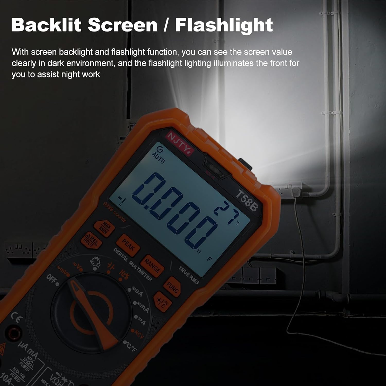
Figure 5.2: The multimeter's backlit screen and integrated flashlight illuminate the display and work area, enhancing visibility in dark environments.
Press the "Lighting/Backlight" button (often marked with a light bulb icon) to turn on the display backlight. Press and hold the same button to activate the flashlight located at the top of the meter. Press again to turn off.
5.10. Automatic Power Off

Figure 5.3: The multimeter features an automatic shutdown function, turning off after approximately 15 minutes of inactivity to conserve battery life.
The multimeter will automatically power off after approximately 15 minutes of inactivity to conserve battery life. An audible voice prompt will sound before shutdown. To restart the meter, press any button or turn the rotary switch.
6. Maintenance
6.1. Cleaning
Wipe the meter with a damp cloth and mild detergent. Do not use abrasives or solvents. Keep the input terminals free of dirt and moisture.
6.2. Battery Replacement
When the low battery indicator appears on the display, replace the batteries as described in Section 4.1. Prompt battery replacement ensures accurate readings.
6.3. Fuse Replacement
If the meter fails to measure current, the fuse may be blown. To replace the fuse:
- Ensure the multimeter is turned OFF and disconnect all test leads.
- Open the battery compartment cover as described in Section 4.1.
- Carefully remove the old fuse.
- Replace with a fuse of the same type and rating:
- For µA mA input: F 600mA/250V
- For 10A input: F 10A/250V
- Replace the battery cover and tighten the screw(s).
7. Troubleshooting
| Problem | Possible Cause | Solution |
|---|---|---|
| Meter does not power on. | Dead or incorrectly installed batteries. | Check battery polarity and replace batteries if necessary (Section 4.1). |
| No reading or "OL" displayed during measurement. | Incorrect range, open circuit, or blown fuse (for current). | Ensure correct function/range. Check test lead connections. For current, check and replace fuse (Section 6.3). Verify circuit continuity. |
| Inaccurate readings. | Low battery, incorrect connection, or external interference. | Replace batteries. Recheck test lead connections. Move away from strong electromagnetic fields. |
| Buzzer does not sound during continuity test. | Circuit resistance is too high. | Ensure resistance is below approximately 50Ω for continuity indication. |
If the problem persists after attempting these solutions, contact customer support.
8. Specifications
The following specifications are for the Irfora T58B Digital Multimeter:
General Specifications:
- Display: 9999 Counts LCD display
- Safety Rating: CAT III 600V, CAT II 1000V
- Pollution Grade: 2
- Working Height: Under 2000m
- Working Temperature: 0-40°C (<80%RH, not considered <10°C)
- Storage Temperature: -10~60°C (<80%RH, remove battery)
- Test/Calibration Ambient Temperature: 20°C ± 2°C
- Maximum Voltage between Measurement End and Ground: 1000V DC or 750V AC
- Fuse Protection:
- For µA mA input: F 600mA/250V
- For 10A input: F 10A/250V
- Conversion Rate: Approximately 3 readings/second
- Overload Display: "OL"
- Power Supply: 3 * 1.5V AAA batteries (Not included)
- Item Size: 187 * 95 * 55mm / 7.36 * 3.74 * 2.16in
- Item Weight: 331g / 11.67oz
Measurement Ranges:
- DC Voltage: 100mV, 600mV, 1V, 60V, 600V, 1000V
- AC Voltage: 100mV, 600mV, 1V, 60V, 600V, 750V
- DC Current: 600µA, 6mA, 60mA, 600mA, 6A, 10A
- AC Current: 600µA, 6mA, 60mA, 600mA, 6A, 10A
- Resistance: 600Ω, 6kΩ, 60kΩ, 600kΩ, 6MΩ, 60MΩ
- Capacitance: 6nF, 60nF, 600nF, 6µF, 60µF, 600µF, 6mF, 60mF
- Frequency: 100Hz, 1KHz, 10KHz, 100KHz, 1MHz, 10MHz, 25MHz
- Temperature: -50°C~1000°C / -58°F~1832°F
- Diode Test: Yes
- Buzzer (Continuity): Yes
9. Warranty and Support
For warranty information or technical support, please refer to the purchase platform or contact Irfora customer service directly. Keep your purchase receipt as proof of purchase.
Contact Information: Please refer to the seller's contact details on the platform where the product was purchased.