1. Introduction
This manual provides detailed instructions for the installation, operation, and maintenance of your CO-Z Dual Arm Swing Gate Opener System, Model SGO-D440-EU. Please read this manual thoroughly before installation and use to ensure proper function and safety. This system is designed to automate dual swing gates, supporting up to 200 kg per leaf and a total gate width of 6 meters.
2. Safety Information
WARNING: Failure to follow these safety instructions may result in serious injury or property damage.
- Ensure all electrical connections are performed by a qualified electrician and comply with local electrical codes.
- Keep children and pets away from the gate area during operation.
- Do not attempt to repair or modify the system components. Contact qualified service personnel for assistance.
- Always disconnect power to the gate opener before performing any maintenance or adjustments.
- Ensure the gate is properly balanced and moves freely before installing the opener.
- Install safety devices such as photocells or safety edges to prevent entrapment.
3. Package Contents
Verify that all components listed below are present in your package:
- 2 x Arm Actuators
- 2 x Manual Release Keys
- 2 x Remote Controls
- 1 x Control Box with Housing
- 4 x Post Base Brackets
- 2 x Post Pivot Brackets
- 2 x Gate End Brackets
- 4 x Gate Tube Brackets and M8 Nuts
- 8 x M10x200 Bolts, Nuts, and Washers
- 8 x M8x70 Bolts, Nuts, and Washers
- 4 x M8x25 Bolts, Nuts, and Washers
- 2 x Mounting Bolts, M8 Nuts
- 2 x Dowels and 8x40 Washers
- 4 x 6.3x25 Self-tapping Screws
- 1 x Limit Stop
- 1 x Instruction Manual (this document)
4. Product Overview
The CO-Z Dual Arm Swing Gate Opener System provides automated control for your swing gates. It features robust construction and flexible power options.

Figure 4.1: Main components of the CO-Z Dual Arm Swing Gate Opener System, including the control box, two arm actuators, and two remote controls.
4.1 Key Features
- AC/DC Power Supply: The system can be powered by a 220V AC household supply or a 24V DC supply using two 12V batteries (not included) or a solar module kit (not included).
- Powerful 40W DC Motors: Each telescopic actuator can operate a gate leaf up to 200 kg and 6 meters in length, with an opening speed of 0.7 meters per minute.
- Customizable Closing Times: Set automatic closing times to 15, 30, 60, or 90 seconds after the gate opens.
- Weather-Resistant Design: Built with an IP44-rated casing to withstand rain, dust, and dirt, operating reliably in temperatures from -20°C to 70°C.
- Safe Operation: Features obstacle detection that stops and reverses the gate if people or vehicles are detected.

Figure 4.2: Overview of the system's intelligent, reliable, and safe features.
4.2 Components and Materials
The system is constructed with high-quality materials for durability and performance.

Figure 4.3: High-quality components including pure copper motors, aluminum actuators, a waterproof control box, and a practical gate stop.

Figure 4.4: Detail of the powerful, all-copper DC motor within the actuator arm.
5. Installation Guide
Proper installation is crucial for the safe and efficient operation of your gate opener. It is recommended to have this system installed by a professional.
5.1 Pre-Installation Checks
- Ensure your gate is structurally sound and operates smoothly manually.
- Confirm that there is adequate space for the gate arms to extend and retract without obstruction.
- Verify that the gate posts are strong enough to support the gate opener arms.
5.2 Mounting the Actuators
The gate opener arms can be installed for either push-to-open or pull-to-open configurations. Refer to the diagrams below for correct mounting positions and dimensions (L1, L2).
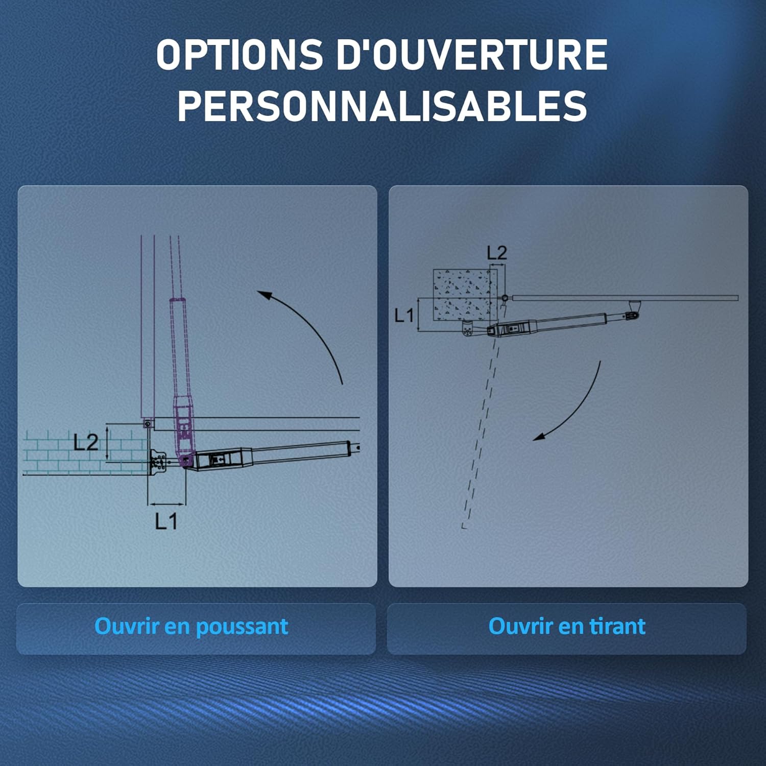
Figure 5.1: Customizable opening options: Push-to-open (left) and Pull-to-open (right).
General Mounting Steps:
- Securely attach the post base brackets to the gate posts.
- With the gate in its fully open position, extend the actuator arm to its maximum retracted length.
- Position the gate end brackets on the gate leaf, ensuring proper alignment with the actuator arm. Mark and drill holes.
- Attach the actuator arms to both the post and gate brackets using the provided bolts, nuts, and washers.
- Install the limit stop to define the gate's closed position.
5.3 Power Supply Options
The system offers versatile power options:
- AC Power: Connect to a standard 220V household power supply.
- DC Battery Power: Use two 12V batteries (not included) for DC operation.
- Solar Power: Integrate with a solar module kit (not included) for sustainable power.

Figure 5.2: Power supply options: household AC, DC batteries, or solar power.
6. Wiring Diagram
A detailed wiring diagram is included in the physical instruction manual provided with your product. Please refer to it for all electrical connections. Ensure all wiring is done correctly to prevent damage to the system and ensure safe operation. Pay close attention to connections for the control board, motors, power supply, and any optional accessories like photocells or keypads.
Note: Incorrect wiring, such as reversing NO (Normally Open) and NC (Normally Closed) connections for safety sensors, can lead to system malfunction or safety hazards. Always double-check your connections against the provided diagram.

Figure 6.1: The control board supports various accessories for a customized system.
7. Operating Instructions
7.1 Remote Control Operation
Your system comes with two remote controls for convenient operation. To open or close the gate, press the designated button on the remote control. The gate will begin to move. Pressing the button again during operation will stop the gate.
7.2 Manual Release
In case of power failure or system malfunction, the gate can be operated manually using the provided manual release keys. Insert the key into the lock on the actuator arm and turn it to disengage the motor, allowing you to open or close the gate by hand.
8. Customizable Settings
8.1 Automatic Closing Time
The system allows you to set an automatic closing delay. After the gate opens, it can be programmed to close automatically after 15, 30, 60, or 90 seconds. Refer to the control box manual for specific programming steps.
8.2 Obstacle Detection
The integrated obstacle detection system enhances safety. If the gate encounters an obstruction (person or vehicle) during closing, it will stop and reverse direction. This feature is designed to prevent injury and damage.
9. Maintenance
Regular maintenance ensures the longevity and reliable operation of your gate opener system.
- Monthly: Check all mounting bolts and screws for tightness. Lubricate moving parts of the gate (hinges, rollers) if necessary.
- Quarterly: Inspect the gate opener arms for any signs of wear, damage, or corrosion. Clean the exterior of the control box and actuator arms.
- Annually: Have a qualified technician inspect the electrical connections and overall system performance.
- Keep the area around the gate clear of debris and vegetation that could obstruct its movement or interfere with sensors.
10. Troubleshooting
If you encounter issues with your gate opener, refer to the following common problems and solutions:
| Problem | Possible Cause | Solution |
|---|---|---|
| Gate does not respond to remote control. | Dead remote battery, remote not programmed, power outage. | Replace remote battery. Reprogram remote (refer to manual). Check main power supply. |
| Gate opens but does not close. | Safety sensors (photocells) obstructed or misaligned, auto-close feature disabled. | Clear obstruction from sensors. Align sensors. Check auto-close settings. |
| Gate stops or reverses unexpectedly. | Obstruction detected, motor overload, faulty sensor. | Remove obstruction. Check gate for free movement. Inspect sensors for damage. |
| System has a wiring error (e.g., X5 terminal and infrared cell). | Incorrect connection of safety sensors. | Refer to the detailed wiring diagram in the included manual. Ensure NO (Normally Open) is connected to PH, not NC (Normally Closed) to PH, for infrared cells. Consult a qualified electrician if unsure. |
11. Specifications
| Feature | Specification |
|---|---|
| Brand | CO-Z |
| Model Number | SGO-D440-EU |
| Product Dimensions (L x W x H) | 71 x 7.5 x 7.9 cm |
| Weight | 9 Kilograms |
| Color | Black |
| Style | 200KG × 2 Arms (DC/AC) |
| Finish | Aluminum |
| Power Type | DC/AC |
| Voltage | 220 Volts |
| Wattage | 40 Watts |
| Installation Method | Screw-in |
| Noise Level | 60 Decibels |
| Max Gate Leaf Weight | 200 kg per arm |
| Max Gate Width | 6 meters (total for two leaves) |
| Opening Speed | 0.7 m/min |
| Operating Temperature | -20°C to 70°C |
| IP Rating | IP44 |
12. Warranty and Support
Your CO-Z Dual Arm Swing Gate Opener System is covered by a standard brand warranty. For specific warranty terms and conditions, please refer to the warranty card included in your package or visit the official CO-Z website.
If you require technical assistance, have questions about installation, or need to report a problem, please contact CO-Z customer support. Contact information can typically be found on the product packaging, the official website, or through your retailer.


